11 minute read
MAINTENANCE


Raw Water Pump
Raw Water Pump Maintenance
The raw water pump does not require any routine maintenance. It is lubricated by engine oil in a metered amount from the end of the auxiliary shaft. However, seasonally, it is a good practice to remove the pump end cover and replace the flexible impeller at the end of the boating season. The end cover of the water pump also needs to be removed to allow any remaining trapped water to be removed before the vessel is stored for winter. The raw water pump body or liner should also be checked for cracks or wear and replaced, if necessary.
A raw water pump seal malfunction is indicated by leakage of water from the openings in the pump housing. These openings, located between the pump mounting flange and the inlet and outlet ports, must remain open at all times. Leaky seals require replacement. Authorized MackPower™ service outlets are properly equipped to perform these services.
Raw Water Pump Impeller Replacement
1.Close the engine sea water seacock.
2.Drain sea water from the raw water cooling system by separating the outlet hose at the raw water pump.
The entire raw water cooling system will drain back through the removed raw water outlet hose. This system contains many gallons of water. Be prepared to catch the water in buckets or allow the bilge pump to pump it out of the hull.
3.Remove the six special brass impeller cover capscrews and remove the end cover by prying off with a gasket scraper. Care should be exercised to avoid scratching or bending the end cover.
Refer to Figure 39.
4.Remove the impeller outer wearplate.
5.Inspect the impeller area and remove any grass, sea weed, impeller pieces, etc., which are present. Also allow any remaining sea water to drain.
6.Grasp hub of impeller (7) with pliers and remove the impeller from bore. If impeller O-ring remains on shaft, remove it from shaft.
7.Remove cam/liner (3) from the pump body.
8.Remove inner wearplate (9).
9.Remove the seal retaining ring (8), taking care not to scratch shaft. Remove carbon portion of seal with tensioning spring attached.
10.Remove bolts securing port adapters to ports. Remove four 5/16″ bolts (11) and lock washers (10) holding the pump body to the bearing housing.
11.Remove pump body (2) from bearing housing and shaft sub-assembly. Remove any remaining gasket material from port adapters.
12.Remove slinger O-ring (1) from shaft.
13.From drive end of pump body, press out remaining portions of seal.
14.Clean and inspect all parts for wear. If wearplates are worn, they should be reversed or replaced. If cam/liner thickness is 3/8″ or less at its thickest section, it should be replaced.

Maintenance
15.Install slinger O-ring (1) on shaft near bearing housing.
16.Lubricate ceramic seal seat boot with WATER ONLY and press into seal bore of pump body. Exposed ceramic surface should face toward impeller bore.
It is extremely important that the seal components do not become soiled during assembly.
17.Slide pump body (with seal seat installed) over shaft, taking care not to dislodge seal seat as body is moved toward (and aligned with) bearing housing. Attach pump body to bearing housing with four 5/16″ bolts and lock washers.
18.Install carbon portion of seal with tensioning spring and spring washer over shaft and locate in seal bore with carbon face against ceramic seal seat. Slide seal retaining ring over shaft against seal thrust ring and locate in retaining ring groove.
19.Install inner wearplate (9) in pump body aligning notch in wearplate with pin in body.
20.Lubricate body with a film of water pump grease and aligning hole in top of cam/liner (3) with pin in pump body (2). Push into body until it is recessed about 1/8″ from end cover surface
21.Liberally grease the inside of cam/liner with water pump grease.
22.Install impeller O-ring in groove in impeller insert. Inserting end of impeller (7) with O-ring first, rotate impeller in direction of pump rotation to bend blades under cam and push into bore until impeller insert flats align with shaft flats. Then push impeller all the way into impeller bore. End of impeller should be approximately even with cam/ liner. Install rubber spline plug into end of impeller.
23.Install outer wearplate ensuring that notch in wearplate aligns with hole in top of cam/liner.
24.Place a new end cover gasket (6) over pin in end cover. Install end cover (5), aligning pin with hole in cam/liner.
25.Insert the six special end cover brass capscrews (4). Tighten the capscrews to specifications.
26.Reconnect the outlet hose at the raw water pump and tighten hose clamp to specification.
27.Open the engine sea water seacock.
Pump will self-prime at low or high speeds. Be sure suction lines are airtight or pump will not self-prime.
Impeller depends on liquid pumped for lubrication. DO NOT RUN DRY for more than 30 seconds. Lack of liquid will burn the impeller.
Gear Oil Cooler
General Information
To clean the internal components of the gear oil cooler, the cooler must be removed from the engine. Cleaning of the gear oil cooler is recommended seasonally before the vessel is stored for the winter or if a cooling deficiency dictates cleaning is required. The gear oil cooler should be replaced every 4,000 hours or 4 years, whichever occurs first.
Cleaning Gear Oil Cooler Internal Components
1.Close the engine sea water seacock.
2.Drain sea water from the raw water cooling system by separating the outlet hose at the raw water pump.
The entire raw water cooling system will drain back through the removed raw water outlet hose. This system contains many gallons of water. Be prepared to catch the water in buckets or allow the bilge pump to pump it out of the hull.
3.Loosen the two closest hose spring clamps to the oil cooler and separate the cooler from the hose which attaches to the heat exchanger and the hose that attaches to the aftercooler tube.
4.Drain the transmission oil cooling lines back to the oil tank and disconnect both the inlet and outlet cooling hoses. Mark the lines for easy reinstallation. Cap lines and cooler fittings to avoid contaminating gear oil.
5.Loosen and remove the clamp which attaches the gear oil cooler to the inlet manifold bracket and remove the oil cooler from the engine.
Figure 40
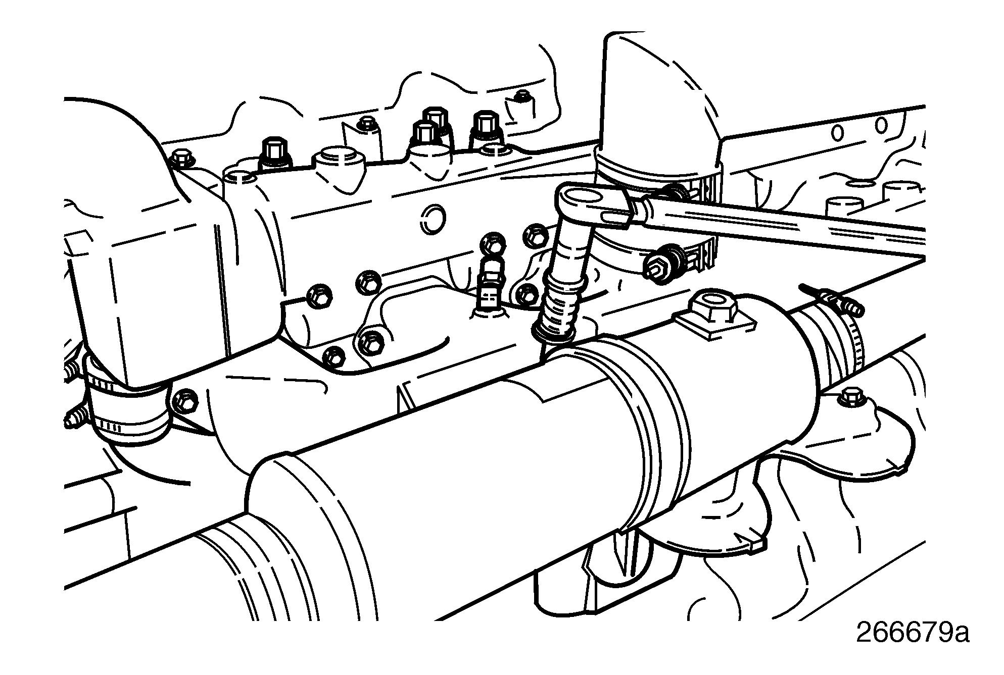
Removing Gear Oil Cooler
6.Circulate a cleaning solvent such as Powercool 2001 On-Line-Cleaner, or equivalent, through the tubes. Drain the cleaner.
7.Clean (rod out) the inside of the tubes of the gear oil cooler using a gun (firearm) cleaning kit or a bore brush. Use a .22 caliber rod with enough extensions to push the tool completely through the tubes. Do not try to reverse direction of the rod as the brush is too large to be reversed in the tube. A pellet gun brush (.18/.19 caliber) should also work. Push the brush through each tube and blow out with compressed air. Only about half of the tubes can be reached for rodding.
8.Position the gear oil cooler on the inlet manifold bracket and install the clamp which attaches the gear oil cooler to the inlet manifold bracket. Tighten to specification.
9.Reattach the transmission oil cooling lines onto the gear oil cooler and tighten line connections to specification.
10.Reattach the gear oil cooler to the hose that attaches to the heat exchanger and the hose that attaches to the aftercooler tube. Position and tighten the hose to specification.
11.Reattach the outlet hose at the raw water pump and position and tighten the clamp to specifications.
12.Open the engine sea water seacock.
Maintenance
Heat Exchanger Maintenance
General Information
The MackPower™ M-E7 engine uses a tube and shell style engine heat exchanger (cooler). The cooler is mounted with connector hoses and clamps between the outlet of the gear cooler discharge raw water pipe and the engine raw water discharge pipe. The engine heat exchanger has removable end caps. The cooler end caps should be removed to allow inspection of the exchanger for damage and plugging of the raw water passages at least once a year. The cooler should be replaced if severe plugging or damage is indicated.
Failure to periodically inspect the cooler for plugging or damage may lead to restricted coolant flow which could result in poor engine performance or engine failure.
CLEANING HEAT EXCHANGER INTERNAL COMPONENTS
1.Close the engine sea water seacock.
2.With the engine at ambient temperature, drain sea water from the raw water cooling system by separating the outlet hose at the raw water pump.
The entire raw water cooling system will drain back through the removed raw water outlet hose. This system contains many gallons of water. Be prepared to catch the water in buckets or allow the bilge pump to pump it out of the hull.
3.Carefully remove the end caps from the cooler. Catch the remaining raw water in a container and discard.
4.Inspect the cooler outer shell for signs of damage or leaks. A cooler showing obvious signs of damage should not be reused.
5.If there are no signs of damage, inspect the cooler tubes for plugging. If tubes are not plugged, replace the end caps with new gaskets and properly tighten. If tubes are plugged, proceed with step 5.
Procedure in step 5 assumes there is adequate room in the boat to clean the unit in place. If this is not possible, remove the unit. Removal instructions are in the following section, Heat Exchanger Removal for Cleaning.
6.Replace the end caps on the unit. Remove the raw water inlet and outlet hose connections to the cooler. Circulate a cleaning solvent such as Powercool 2001 On-Line-Cleaner, or equivalent, through the tubes. Drain the cleaner and remove the end caps.
7.Clean (rod out) the inside of the tubes of the heat exchanger using a gun (firearm) cleaning kit or a bore brush. Use a .22 caliber rod with enough extensions to push the rod completely through the tubes. Do not try to reverse direction of the rod as the brush is too large to be reversed in the tube. A pellet gun brush (.18/.19 caliber) should also work. Push the brush through each tube and flush out any loosened material with clean, fresh water.
8.Drain water from cooler tubes and blow dry with compressed air.
To avoid possible injury when using compressed air, wear required safety equipment (face plate or safety glasses) and do not exceed 40 psi (276 kpa) air pressure.
9.Reinstall end caps with new gaskets and properly tighten.
10.Reattach the heat exchanger raw water connections, being sure to fully slide the hoses on the heat exchanger nipples. Tighten hose clamps to specification.
11.Reattach the outlet hose at the raw water pump and position and tighten the clamp to specifications.
12.Open the engine sea water seacock.
13.Start the engine and check for leaks.
Pump will self-prime at low or high speeds. Be sure suction lines are airtight or pump will not self-prime.
Impeller depends on liquid pumped for lubrication. DO NOT RUN DRY for more than 30 seconds. Lack of liquid will burn the impeller.
Heat Exchanger Removal For Cleaning
1.Close the engine sea water seacock.
2.Drain the raw water side of the system as previously outlined. Loosen the hose spring clamps and separate the hose which attaches the heat exchanger to the gear oil cooler outlet. Then loosen the hose spring clamps and separate the hose which attaches the heat exchanger outlet to the raw water exit pipe (mixer).
3.Loosen the engine coolant drain cock on the heat exchanger to engine oil cooler inlet tube. Catch engine coolant in an approved container and save for reuse. Drain coolant to level below heat exchanger.
Loosening and removing the heat exchanger fill cap will allow the coolant to drain from the cooler inlet tube much faster as this allows the heat exchanger to vent.
7.Inspect
8.If there are no signs of damage, inspect the cooler tubes for plugging. If tubes are not plugged, replace the end caps with new gaskets and properly tighten. Reassemble heat exchanger to engine following the installation instructions. If plugged, proceed with step 8.
9.Replace the end caps on the unit. Circulate a cleaning solvent such as Powercool 2001 On-Line-Cleaner, or equivalent, through the raw water tubes. Drain the cleaner and remove the end caps.
10.Clean (rod out) the inside of the tubes of the heat exchanger using a gun (firearm) cleaning kit or a bore brush. Use a .22 caliber rod with enough extensions to push completely through the tubes. Do not try to reverse direction of the rod as the brush is too large to be reversed in the tube. A pellet gun brush (.18/.19 caliber) should also work. Push the brush through each tube and flush out any loosened material with clean, fresh water.
11.Drain water from cooler tubes and blow dry with compressed air.
To avoid possible injury when using compressed air, wear required safety equipment (face plate or safety glasses) and do not exceed 40 psi (276 kpa) air pressure.
Heat Exchanger Installation After Cleaning
1.Install the heat exchanger end covers with new rubber seals and tighten the center bolt to specification.
2.Install the heat exchanger unit onto the front engine bracket. Position and attach the hoses which connect the heat exchanger to the engine oil cooler inlet tube and the engine thermostat housing. Install the spring-type hose clamps to the tubes. Tighten the spring clamps to specification. Also install the two clamps that secure the heat exchanger to the front mounting bracket and tighten to specification. Make sure rubber isolators are in place.
Maintenance
3.Reattach the hose which connects the heat exchanger to the gear oil cooler outlet and install the hose spring clamp. Tighten to specification.
4.Reattach the hose which connects the heat exchanger outlet to the raw water exit pipe (mixer) and install the hose spring clamp. Tighten the spring clamp to specification.
5.Reattach the outlet hose at the raw water pump and position and tighten the clamp to specifications.
6.Open the engine sea water seacock.
Pump will self-prime at low or high speeds. Be sure suction lines are airtight or pump will not self-prime.
Impeller depends on liquid pumped for lubrication. DO NOT RUN DRY for more than 30 seconds. Lack of liquid will burn the impeller.
Zinc Replacement
General Information
The four zincs in the raw water cooling system provide an anodic reaction with the sea water. This reaction provides electrochemical corrosion protection in which the zinc metal dissolves in the sea water to form positively charged ions. These ions protect the metal of the raw water system cooling components in much the same way the coolant conditioner protects the internal cooling components of the engine. The zincs should be checked initially every 60 days, then as required or annually. Zincs should be replaced when they reach 50% of original size. If zincs are not replaced, clean surface with a wire brush to restore good operation.
The zincs are located in three main components: r Gear Oil Cooler (Contains One Zinc) r Heat Exchanger (Contains One Zinc) r Aftercooler (Contains Two Zincs)
Checking of the heat exchanger is recommended seasonally before the vessel is stored for the winter or at least once per year for vessels used year-round.
Zinc Replacement Procedures
1.Close the engine sea water seacocks.
2.Drain sea water from the raw water cooling system by separating the outlet hose at the raw water pump.
The entire raw water cooling system will drain back through the removed raw water outlet hose. This system contains many gallons of water. Be prepared to catch the water in buckets or allow the bilge pump to pump it out of the hull.
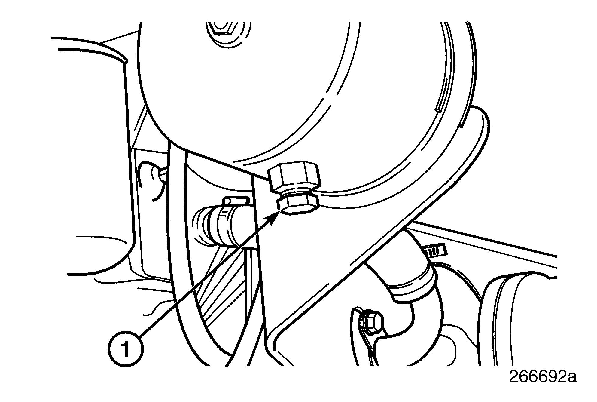
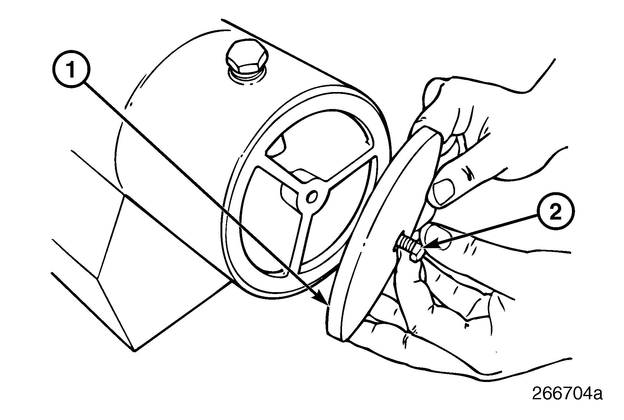
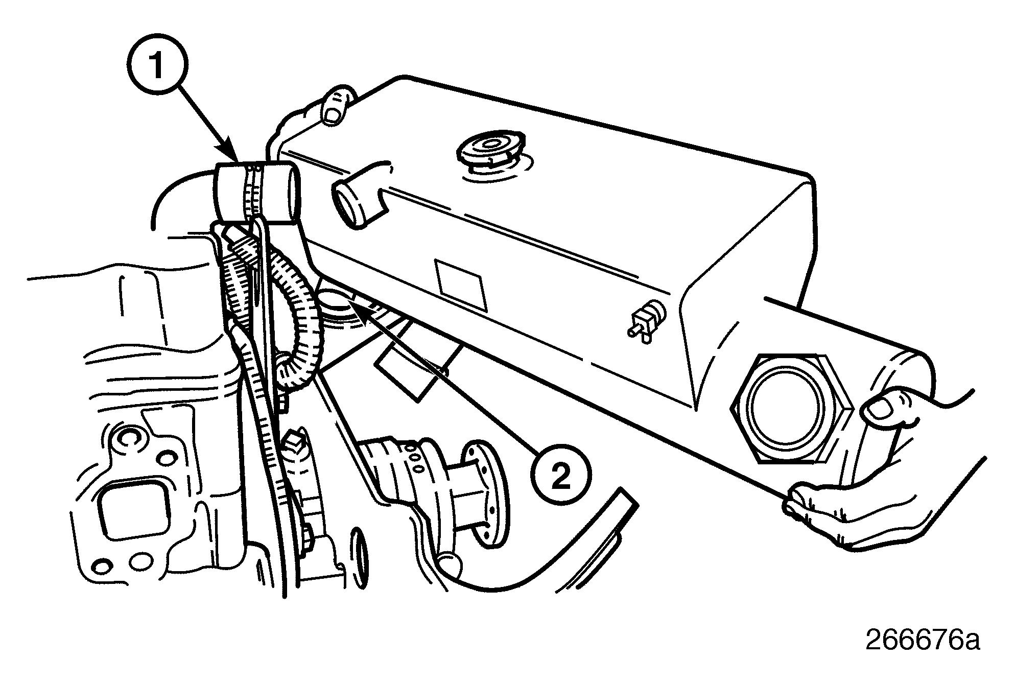
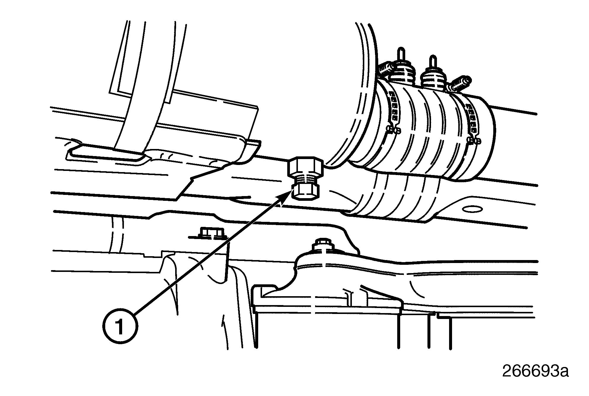
3.Loosen the hex head and remove the zinc located in the right side of the heat exchanger. Inspect zinc and replace or reuse depending on wear. Coat a couple of threads with Loctite® 277 or equivalent/ Teflon® thread sealer and reinstall in heat exchanger. Torque to specifications. Do not coat all engaged threads as electrical conductivity from zinc button to engine component is required. After installation, check conductivity from zinc plug to engine component with a continuity tester.
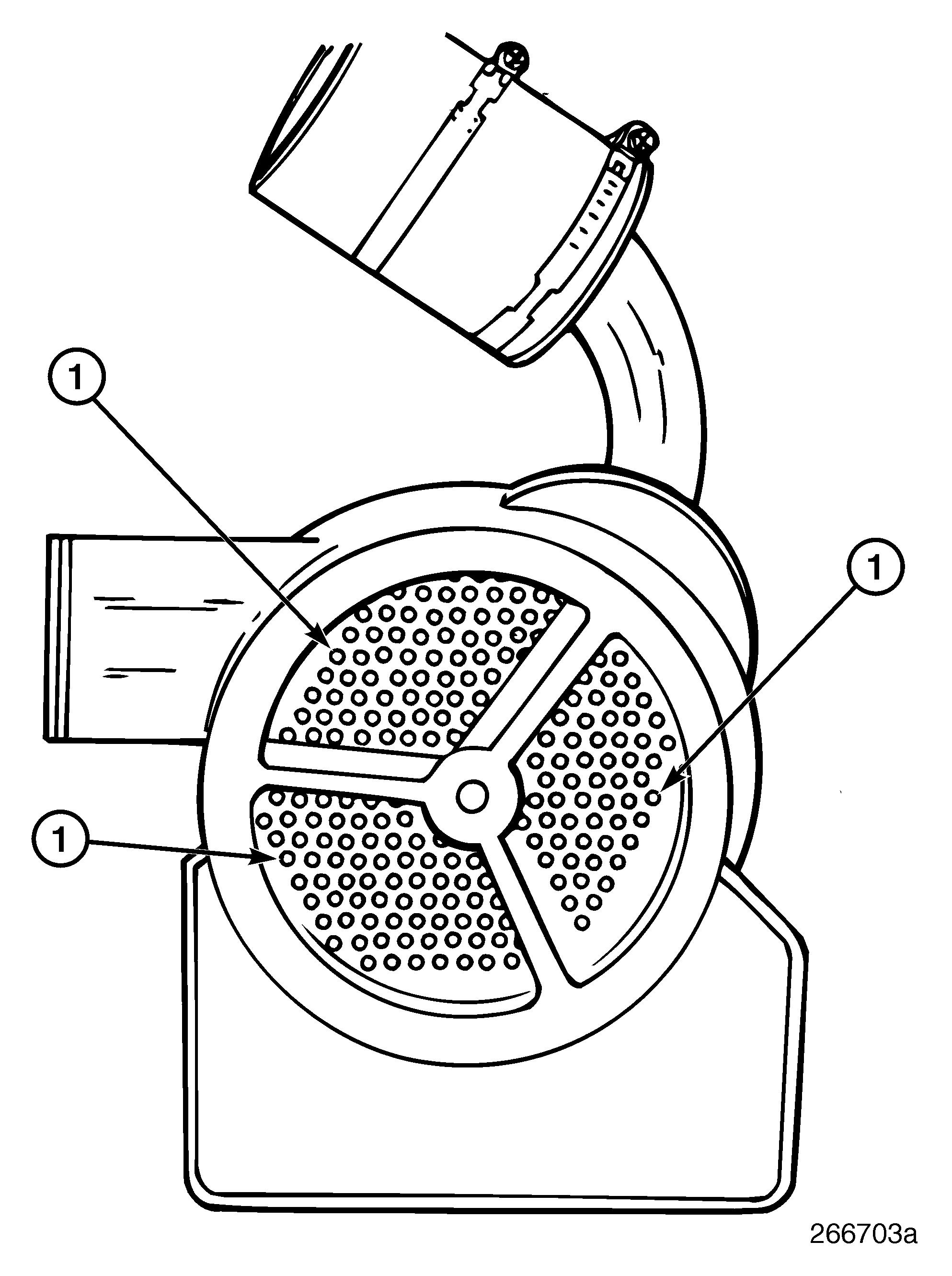
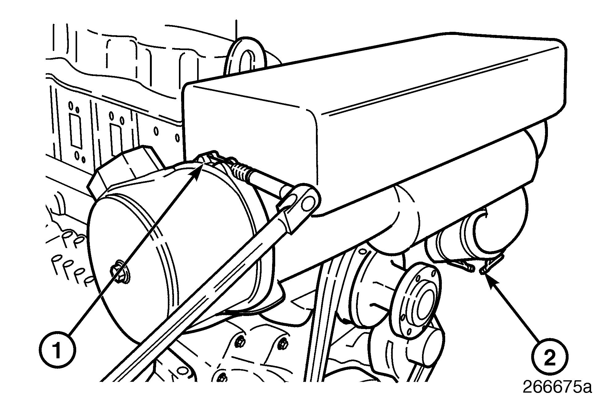
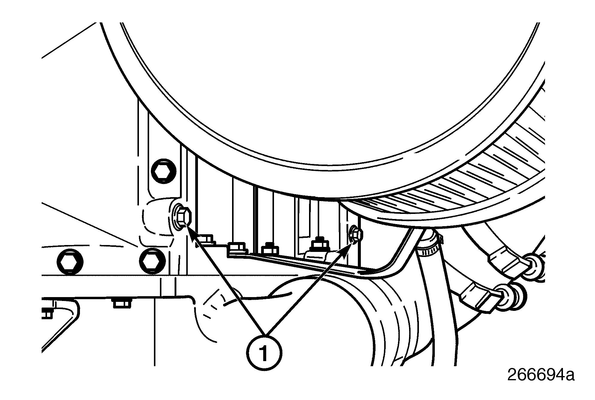
5.Loosen the hex heads and remove the zincs located in the rear of the aftercooler. Inspect zinc and replace or reuse depending on wear. Coat threads with Loctite® 277 or equivalent/Teflon® thread sealer and reinstall in the aftercooler. Torque to specifications. Follow conductivity precaution in step 3. 50
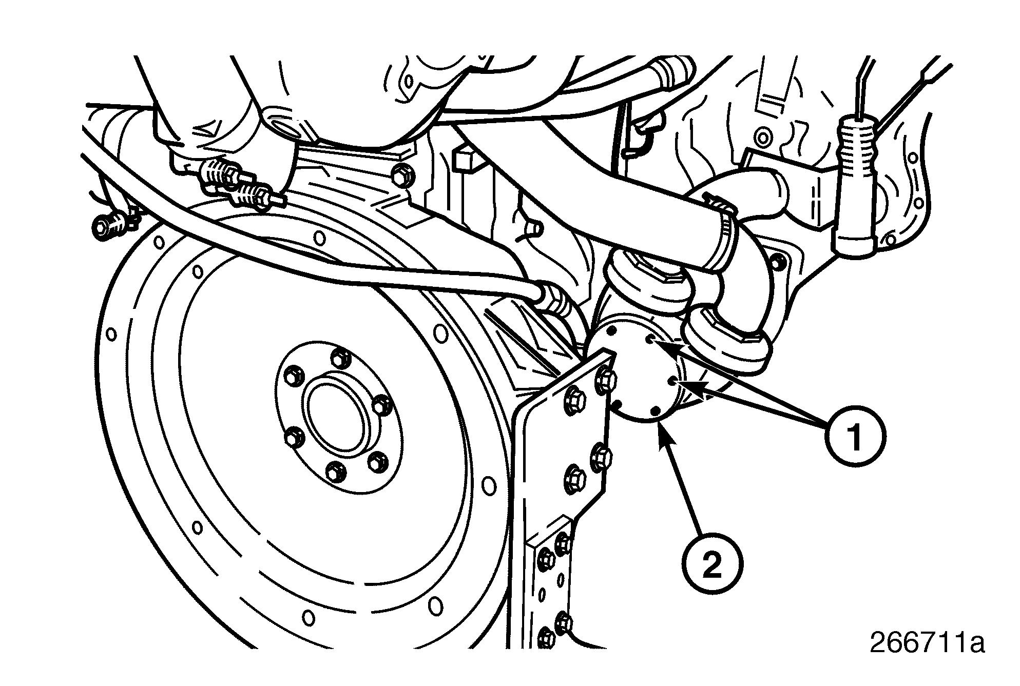
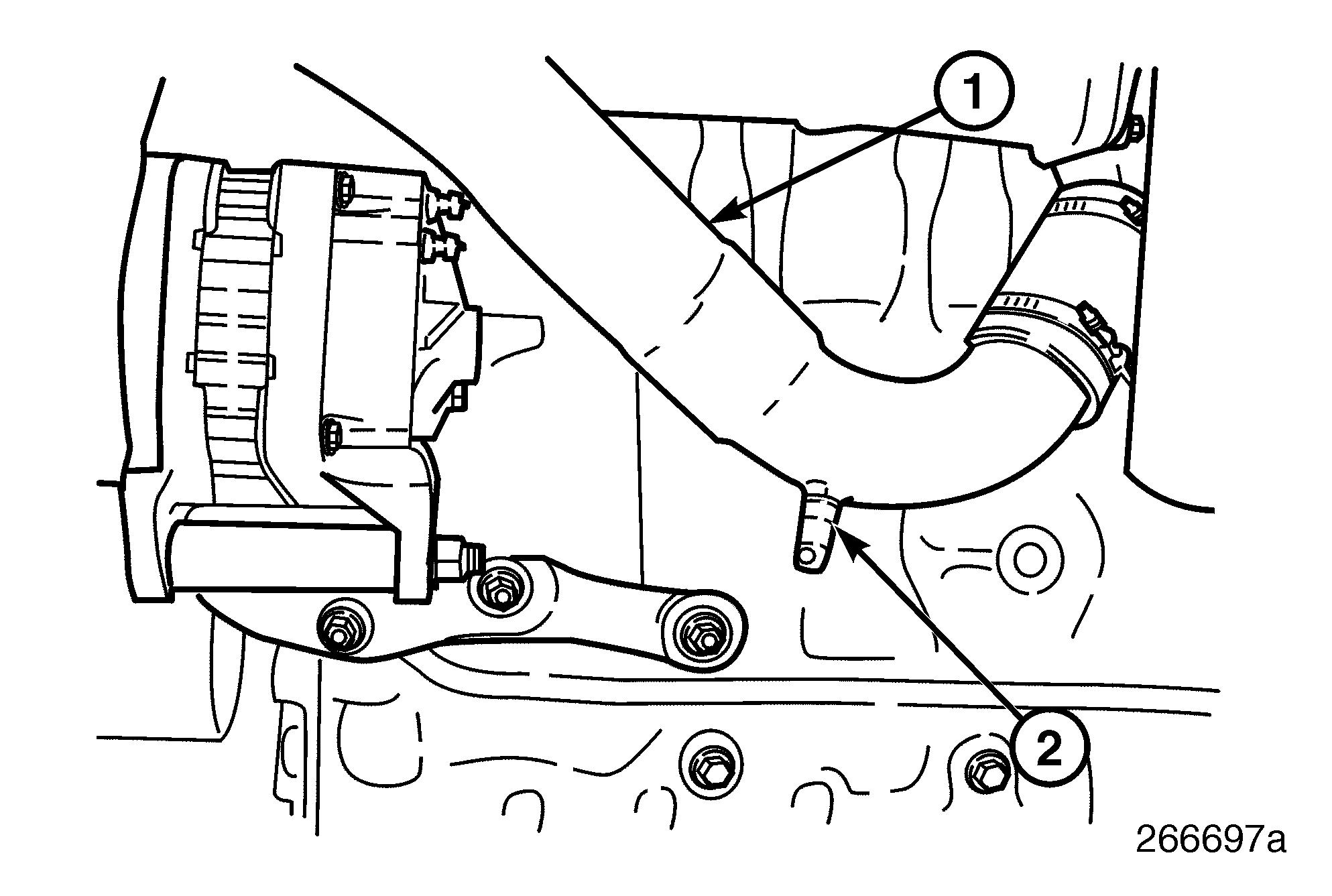
4.Loosen the hex head and remove the zinc located in the gear oil cooler. Inspect zinc and replace or reuse depending on wear. Coat threads with Loctite® 277 or equivalent/ Teflon® thread sealer and reinstall in gear oil cooler. Torque to specifications. Follow conductivity precaution in step 3.
6.Reattach the outlet hose at the raw water pump and position and tighten the clamp to specifications.
7.Open the engine sea water seacock.