15 minute read
TROUBLESHOOTING


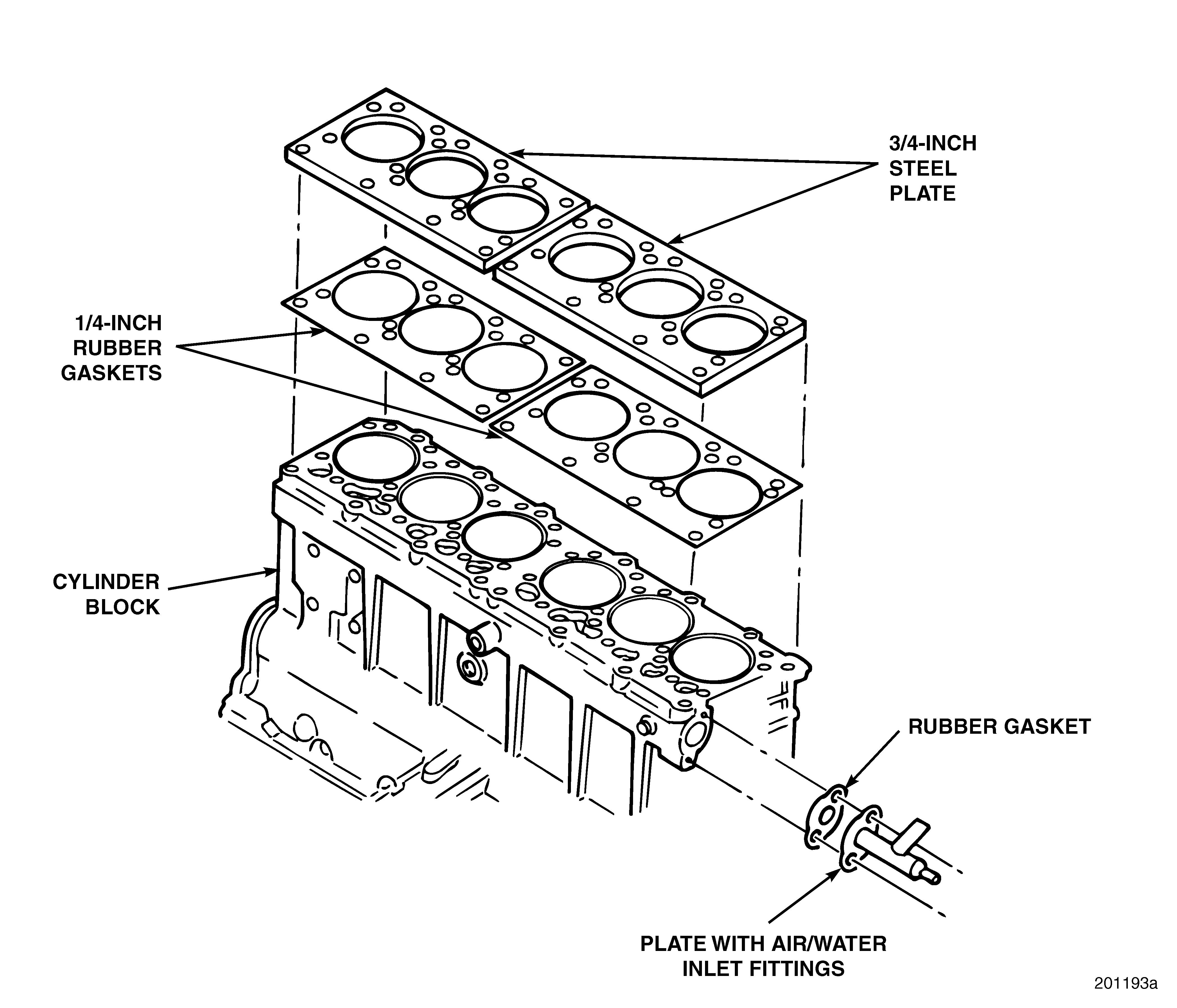
Cylinder Block Coolant Passage Leak Check (Cylinder Heads Removed)
Refer to Figure 14.
1.Fabricate two 3/4-inch-thick (19.1 mm) steel plates to simulate cylinder heads. The plates must have cutouts for the head capscrews and liners. Use a 1/4-inch (6.4 mm) rubber gasket as a seal. Install the plates onto the cylinder head.
As an alternative to step 1, conduct the test using two known leak-free cylinder heads complete with gaskets and fire rings in place of the steel plates. With this alternative, a water manifold (with the outlet end sealed) can be used to seal off the cylinder head coolant ports. Fittings can be installed on the water manifold to introduce the heated water and air pressure needed for the test.
2.Remove water pump assembly and seal opening with a suitable plate and rubber gasket. The plate must be fabricated so that water heated to 150°F (66°Χ) and pressurized to 50 psi (345 kPa) can be introduced into the system.
3.Apply approximately 50 psi (345 kPa) air pressure into the cooling system. Visually inspect the cylinder block for signs of air and water leaks.
Do not exceed 50 psi (345 kPa). Damage to seals or cup plugs may result.
Maintenance
Marine Engine Service Intervals
It is recommended that the following items be checked each day prior to starting the engine. The oil pressure should be checked each day immediately after start-up.
The following is intended as a guide for establishing preventive maintenance intervals. The recommendations given should be followed as closely as possible to obtain long and optimum performance from your MackPower™ engine. Intervals indicated on the chart are time (hours) of actual operation.
1. Lubricating Oil*
2. Fuel and Fuel Tank*
3. Fuel Lines and Flexible Hoses*
4. Cooling System*
5. Turbocharger, Exhaust Connections*
6. Air System, Cleaners*
7. Fuel/Water Separator and Filter*
8. Oil Pressure*
9. Raw Water Pump*
* See item in text.
The intervals shown apply only to the maintenance functions described. These functions should be coordinated with other regularly scheduled vessel maintenance.
The “daily” instructions apply to routine or daily starting of an engine. They do not apply to a new engine or one that has not been operated for a considerable period of time. Follow instructions given under Preparations for Starting the Engine the First Time.
MARINE ENGINE PREVENTIVE MAINTENANCE
DAILY SCHEDULE
Maintenance Item
MARINE ENGINE SERVICE INTERVALS
ComponentInterval
Lube Oil150 hrs.
Lube Oil Filters150 hrs.
Coolant Conditioner150 hrs.
Fuel Filters150 hrs.
Fuel Filters/Water Separators150 hrs.
Coolant Drain1,000 hrs. or 1 year Pleasure Craft 4,000 hrs. or 2 years Commercial Vessel
Air Filter and Vacuum LimiterClean when restriction indicator is red, at 250 hrs., or once per season, whichever occurs first. Replace after three cleanings.
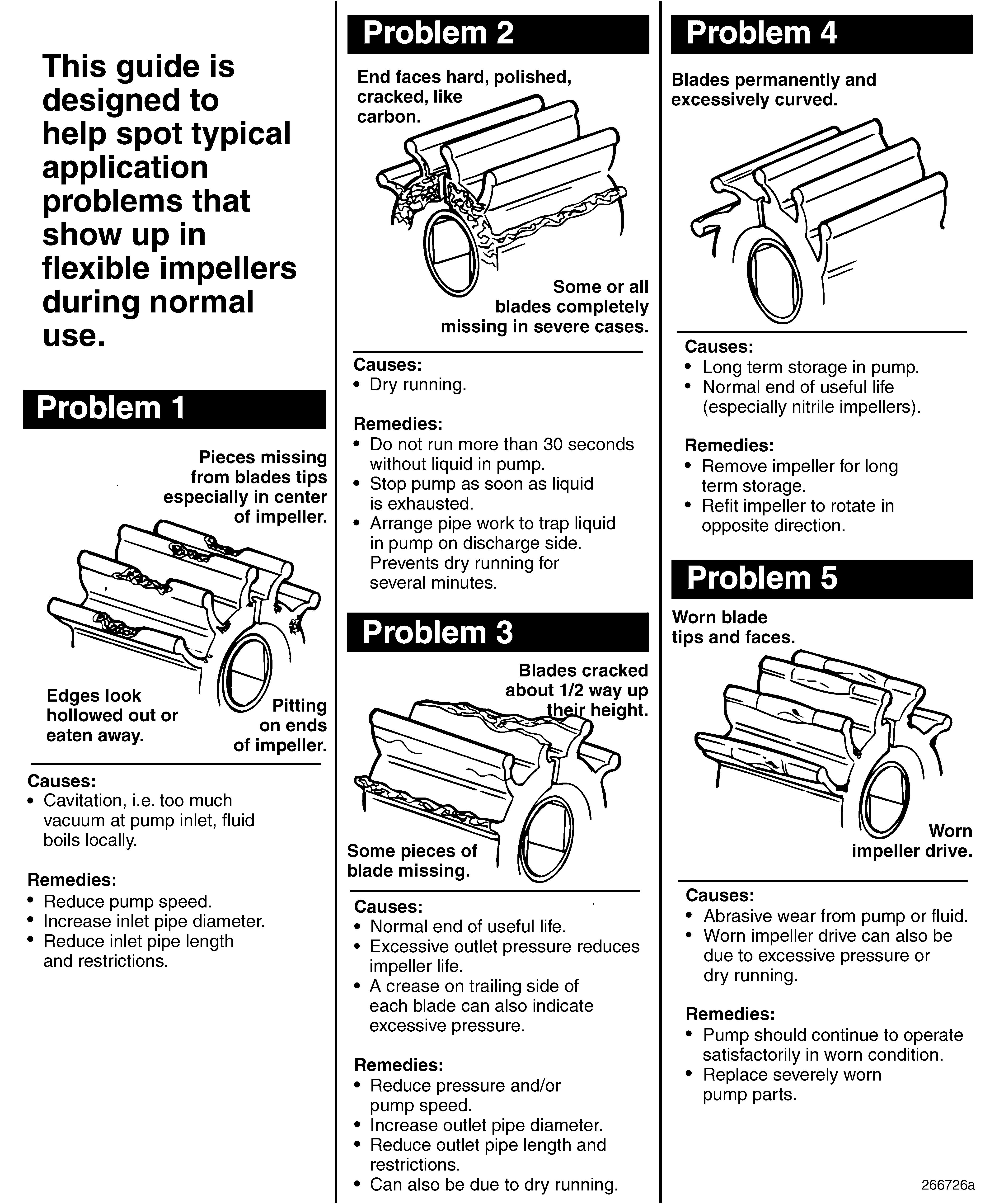
Raw Water Pump ImpellerSubjective, but replace at least once per season.
Raw Water ZincsCheck initially every 60 days, then as required or annually. Replace when reduced to 50% of original size.
Heat ExchangerInspect and clean once per season.
Fuel InjectorsInspect for proper opening pressure and spray pattern every 3000 hrs.
General Maintenance Requirements
Turbocharger and Exhaust Connections
To avoid personal injury or turbocharger damage, do not remove, attach or tighten turbocharger air intake ducting while the engine is operating or operate the engine with the ducting removed.
Visually inspect the mountings, intake and exhaust ducting and connections for leaks daily. Check the oil inlet and outlet lines for leaks or restrictions to oil flow. Check for unusual noise or vibration and, if excessive, stop the engine and do not operate until the cause is determined.
Every 12 months, the exhaust retaining nuts, exhaust flange clamp and other manifold connections should also be checked for leakage and tightened, if necessary.
If so equipped, check heat-insulating exhaust system blankets for damage daily. Torn, matted, crushed, oil-soaked or otherwise damaged insulation blankets must be replaced immediately.
Belt Drive System Maintenance
In order to obtain maximum belt life, proper maintenance, installation and adjustment procedures must be followed. Drive belt tension should be checked every 150 hours and adjusted, if necessary. Periodically check belts for splits, cracks and glazing. Replace any belts as needed.
Maintenance
r Check the belt tension when performing preventive maintenance inspections. If tension is less than 75 lbs. (33 daN), increase belt tension to 110–120 lbs. (49–53 daN).
If belts squeak or squeal, clean belts with an approved cleaning fluid. Replace belts that are severely worn, frayed, cracked or glazed.
Installation
1.When identical belts are used on the same drive, the belts must be replaced as a matched set. (MackPower™ M-E7 marine engines use matched set belts for alternator and water pump drive.)
2.To install belts, shorten the distance between the pulley centers and place the belts over the pulleys without force. Do not pry a belt over a pulley.
3.Misalignment of pulleys should not exceed 1/16 inch (1.6 mm) for each foot of distance between pulley centers.
4.Belts should not bottom in the pulley grooves or protrude in excess of 3/32 inch (2.4 mm) above top edge of the grooves.
5.Belt riding depth should not vary more than 1/16 inch (1.6 mm) on matched belt sets. Belts should not rub against any adjacent parts of the engine.
6.Sharp edges on the pulley grooves will produce excessive wear and premature failure of a V-belt. Care should be taken, especially with machined pulleys, to make sure that a radius of at least 1/16 inch (1.6 mm) is obtained at the outer edge of the grooves.
Adjustment
When installing new belts, initially tighten them between 130–150 lbs. (58–67 daN) gauge reading.
For consistent measurements, use belt tension gauge BT-3373-F, or equivalent, to check the belt tension.
1.Check at the center of the longest span, and chalk-mark
2.Run the engine approximately 5 to 10 minutes, allow the belts to cool, then recheck belt tension at the same chalk-mark point with the chalk-mark in the center of the longest span. If the belt tension is less than 100 lbs. (45 daN), tighten to approximately 110–120 lbs. (49–53 daN).

For belts already in service, retension to 110–120 lbs. (49–53 daN) when tension drops below 75 lbs. (33 daN).
Blow-By Recirculation Unit
GENERAL INFORMATION
Replace or clean the filter and vacuum limiter when the air inlet restriction indicator turns red. This indicates the maximum allowable system restriction has been reached. Replace the filter and vacuum limiter every two years or 1,500 hours of engine operation (whichever occurs first), regardless of apparent condition. The air filter and vacuum regulator filter should be replaced after three cleanings.
BLOW-BY RECIRCULATION FILTER AIR FILTER SERVICING
People often ask why an air filter is needed. The answer is: pollution. The truth is that most boaters operate their boats in urban areas close to shore where there is more dirt in the air than they realize. It doesn’t take long to see the dirt building up on the air filters.
Most pleasure craft owners should clean their filters each boating season. Proper care of your air filter is so important that this whole page is committed to instructing you on the proper method of cleaning them. For best results (and to avoid damage to your AIRSEP® and vacuum regulator air filters), use only the Walker Cleaning and Re-Oiling Kit (part No. DDF9000). For information, contact your local Walker AIRSEP® dealer. Failure to clean the AIRSEP® filter and the vacuum regulator/limiter will affect the operation of the AIRSEP® and may cause damage to the engine.
A filter that is damaged or clogged with soot due to an exhaust leak may not be able to be cleaned to maximum flow condition. Replacement of the element may be necessary.
1. Pre-Cleaning
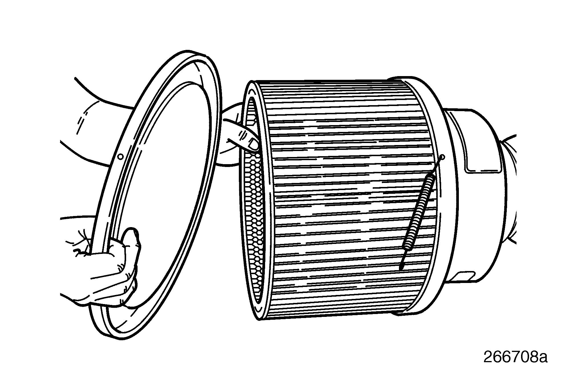
Release the air filter element from the AIRSEP® by removing the four long springs securing the cover and filter onto the blowby recirculation unit housing using pliers, as shown in Figure 17. Tap the filter element to dislodge any large embedded particles or dirt. Then gently brush the filter element with a soft bristle brush. (Note: If complete cleaning at this time is impractical, you may re-oil and reinstall the air filter element.)
2. Spray On Cleaner
Each bottle of Walker Cleaning Solution is good for four filter cleanings when using a standard size filter. Spray the cleaning solution on the filter elements. Filter elements can be rolled or soaked in a shallow pan of solution for 10 minutes (dilute the solution with a small amount of water).
Do not use the following methods or liquids for cleaning the filter element: r NO GASOLINE CLEANING r NO STEAM CLEANING r NO CAUSTIC CLEANING SOLUTIONS r NO HIGH PRESSURE WATER OR AIR r NO PARTS-CLEANING SOLVENTS
3. Rinse Off
Rinse off the filter element with low water pressure. Tap water is O.K. Always flush from the clean side to the dirty side. This will remove the particles and dirt, and not drive it into the filter.
4. Drying the Filter
After rinsing, shake off all the excess water and let the filter element dry naturally. (Leaving outside in the sun will speed the process.) Do not do the following: r DO NOT USE COMPRESSED AIR. r DO NOT USE OPEN FLAME. r DO NOT USE HEAT DRYERS.
5. Re-Oiling the Filter
After cleaning, always re-oil the filter element with Walker Air Filter Oil before using. The effectiveness of the air filter is greatly reduced if it is used without oiling. Sparingly squeeze small amounts of the oil out of the bottle across the top of each pleat. Let the oil wick into the filter element for 20 minutes. Then re-oil any white spots that are still showing.
Do not use any of the following lubricants to re-oil the filter element: r NEVER USE AUTOMATIC TRANSMISSION FLUID. r NEVER USE MOTOR OIL. r NEVER USE DIESEL FUEL. r NEVER USE WD-40®, OR ANY OTHER LIGHTWEIGHT OIL.
6. Maintenance Schedule
The Walker AIRSEP® Air Filter Element should be cleaned every 250 hours of operation or once a year, whichever comes first. The air filter element should be replaced after three cleanings. The vacuum regulator/limiter must also be cleaned every 250 hours, as described below.
In addition to the regular maintenance schedule, the air filter element and vacuum regulator/limiter filter must be cleaned any time the restriction gauge on the AIRSEP® turns red.
7. Cleaning the Vacuum Regulator/Limiter
The vacuum regulator/limiter filter can be cleaned without removing the regulator from the system. Using a standard blade screwdriver, undo the filter and follow steps 1 through 5. Reinstall the filter when done. To clean the vacuum limiter, do not attempt to remove the filter. Remove and clean the entire unit by simply following the same cleaning and oiling steps listed above steps 1 through 5. Reinstall the unit when done.
The Walker cleaning kit cleans up to four 9″ x 12″ elements. Order part No. DDF9000.
18
8. Resetting the Air Restriction Gauge
If the filter is being replaced due to the air restriction gauge indicating filter capacity is totally used, the filter restriction gauge needs to be reset by pressing the reset button on top of the gauge.

Engine Oil Level Check
As the operator of this vessel, it is important for you to perform the daily inspections necessary to keep your boat in good shape. Maintaining the proper oil level in your engine crankcase cannot be overemphasized.
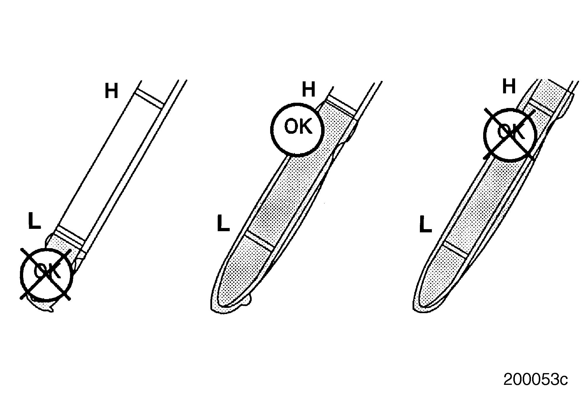
Before checking the oil, remember these important points: r Measurement of the oil level must be taken on calm seas and with the bilge evacuated. r If the engine has been running, allow about 15 minutes after shutdown for oil to drain down to the oil pan. r The level must be close to the FULL line (at least between the ADD and FULL lines) on the dipstick, but must NOT exceed the FULL line (refer to illustration below).
19
Engine Oil Maintenance Requirements
LUBRICATING OIL
Check the oil level daily with the engine stopped. If necessary, add sufficient oil to raise the level to the proper mark on the dipstick. All diesel engines are designed to use some oil, so the periodic addition of oil is normal.
If the oil level is constantly above normal, and excess lube oil has not been added to the crankcase, consult with an authorized MackPower™ service outlet for the cause. Fuel or coolant dilution of lube oil can result in serious damage.
Lube oil is normally changed every 150 hours. Before adding lube oil, refer to the Lubrication Oil guide.
Oil Pressure Check
Under normal operation, oil pressure is noted each time the engine is started. If the engine is equipped with a warning light instead of a pressure gauge, have the oil pressure checked and recorded every 500 hours.
When to Change the Oil
During use, engine lubricating oil undergoes deterioration from combustion byproducts and contamination by the engine. Certain components in a lubricant additive package are designed to deplete with use. For this reason, regardless of the oil formulation, regular oil drain intervals are necessary. These intervals may vary in length, depending on engine operation, fuel quality and lubricant quality. Generally, shorter oil drain intervals extend engine life through prompt replenishment of the protection qualities in the lubricant.
The oil drain intervals should be scheduled so as not to exceed 150 hours of operation. Always install new engine oil filters when the oil is changed.
Used Lubricating Oil Analysis
A used oil analysis program is recommended for monitoring crankcase oil in all engines. Oil analysis consists of a series of laboratory tests conducted on the engine lubricant. Since an oil analysis cannot completely assess the lubricating oil for continued service, it should not be used to extend oil drain intervals.
Dispose of used lubricating oil, filter and gasket in an environmentally approved manner according to state and/or federal (EPA) recommendations.
The Use of High Sulfur Fuels
The combustion of high sulfur fuels (greater than 0.5% sulfur) will shorten engine life through accelerated wear out of piston rings. High sulfur fuel forms acids during combustion, particularly during idling and low temperature operation. The best defense against the effects of high sulfur fuel is to shorten oil drain intervals. The proper drain interval may be determined by oil analysis.
OIL FILTER ELEMENT AND CENTRI-MAX® FILTER REPLACEMENT
SPECIAL TOOLS REQUIRED r Fuel and Oil Filter Wrench J 24783 r Oil Filter Wrench J 29927
General Information
Lubricating oil filters should be changed whenever the engine oil is changed. Before changing filters, consult with an authorized MackPower™ service outlet for required part number.
The oil filter mounting adapter is designed to accommodate a poppet-style relief valve. When performing an oil and filter change, it is suggested that the function of the poppet-style relief valve be checked by pushing against the viton disk to verify spring tension.
Disposable Spin-On Oil Filter Replacement
Change oil and replace oil filters at every 150 hours of service using the following procedure:
1.Run the engine until normal operating temperature is reached. Then, shut off the engine and drain the oil before the engine cools.
2.Thoroughly clean the area around the filters before removing.
3.Using tool J 24783, or equivalent, remove both spin-on filters and wipe the filter mounting base clean.
4.Prefill each filter with 2 quarts (1.9 liters) of the specified engine oil. DO NOT allow any contaminants to enter the filters while prefilling.
5.Apply a film of clean engine oil to the sealing gasket on each new filter.
6.Install the filters and tighten 3/4 to 1 turn after the gasket contacts the base.
7.Fill the crankcase with the recommended engine oil.
8.Start the engine and check for leaks. Run the engine for approximately five minutes, then shut it off and recheck the oil level. Add oil if necessary.
Use of anything other than genuine MACK filters may cause damage and void the engine warranty. Change filters according to the recommended maintenance schedule.
Centri-Max® Filter Assembly
There are different style rotors used in the Centri-Max® assembly. As such, it is important that the proper rotor be used in the Centri-Max® unit for which it was designed. The MackPower™ M-E7 marine engine uses the externally drained swept rotor design.
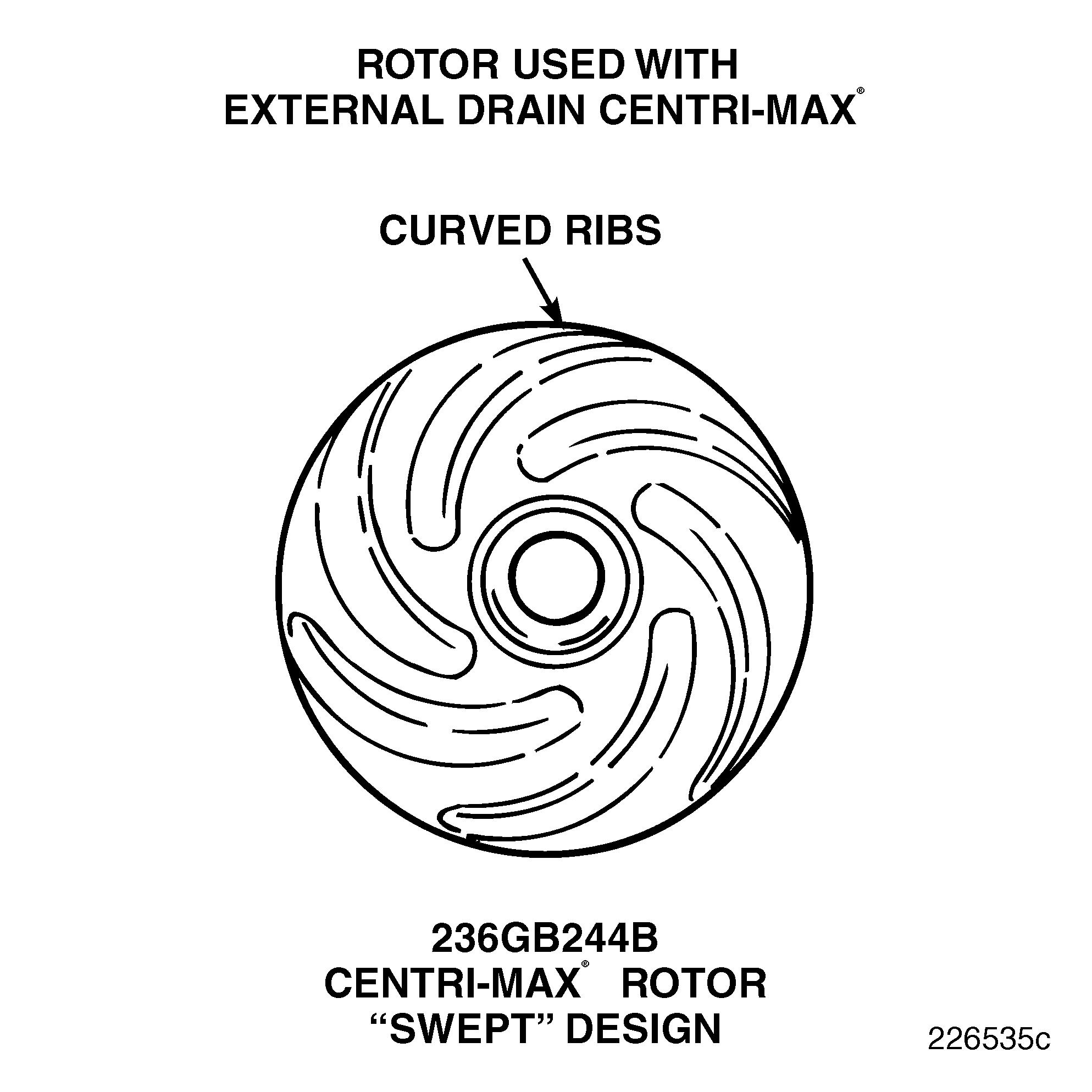
The more efficient “swept” rotor (part No. 236GB244B) was implemented into production with the first M-E7. The swept rotor is easily identified by the ribs on the rounded end, which are curved rather than straight. 20
5.Remove and discard the filter seal and rotor. Clean the filter housing.
6.Install a new filter seal and rotor in the filter housing.
7.Apply a thin film of engine oil to the sealing gasket. Install the centrifugal filter housing and tighten the housing BY HAND an additional 3/4 turn after the gasket contacts the base.
8.Install the drain hose on the base of the filter housing and tighten the hose clamps at the cylinder block and filter housing.
9.Start the engine and check for leaks.
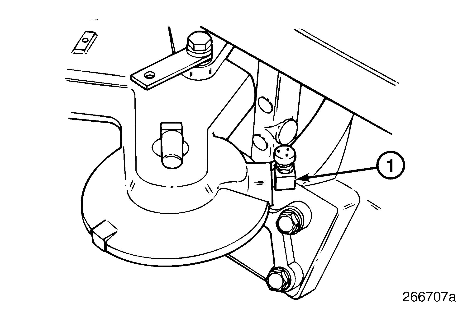
Oil Filter Mounting Bracket Breather Vent
The oil filter mounting bracket contains a breather vent. This vent should be periodically checked to be sure it is open and not blocked by dust or debris. Checking of the breather is recommended at the same time as the oil filters are being replaced. 21
Centri-Max® Filter Replacement
1.Clean the area around the centrifugal filter before removing the drain hose.
2.Loosen the hose clamp at the bottom of the filter housing and disconnect the drain hose.
3.Loosen the hose clamp at the cylinder block drain and rotate the hose out of the way.
4.Using tool J 24783, remove the centrifugal oil filter housing.
Be sure to apply the filter removal tool on the filter housing at the point marked “WRENCH HERE.”
Fuel System Maintenance
Drain the water from the fuel/water separator daily or as required. Primary and secondary fuel filters should be replaced every 150 hours or annually, whichever occurs first (or sooner if plugging is indicated).
FUEL PRIMARY FILTER REPLACEMENT (ON HULL FRAMING, TRANSOM OR BULKHEAD)
The spin-on type consists of a shell, element and gasket unitized into a single cartridge and a strainer or filter cover which includes a threaded sleeve to accept the spin-on filter cartridge.
1.Thoroughly wash the area around the fuel filter and mounting adapter mating area with a suitable solvent and blow dry the area with compressed air.
2.With the engine shut down, place a suitable container under the strainer or filter and remove the used fuel filter using filter wrench J 24783. Dispose of the cartridge in an environmentally responsible manner according to state and/or federal (EPA) recommendations.
Install primary fuel filter using the following procedure.
1.Wipe the filter mounting base clean.
2.Apply a film of clean engine oil to the sealing gasket.
3.Fill the new replacement filter cartridge with clean fuel. Coat the seal gasket lightly with clean fuel.
General field practice is to prime the fuel filters before installation. This practice can allow dirt to enter the outlet port of the filter if caution is not used. Use filtered fuel only when priming the filter. Prime through the series of small holes on the top of the filter. DO NOT prime the filter through the center hole.
4.Install the filter and tighten 3/4 to 1 turn after gasket contacts the base.
5.Start the engine and check for leaks.
If the engine fails to start after installing new fuel filters, refer to Systems Check and Lubrication under Final Preparation and Operational Check.
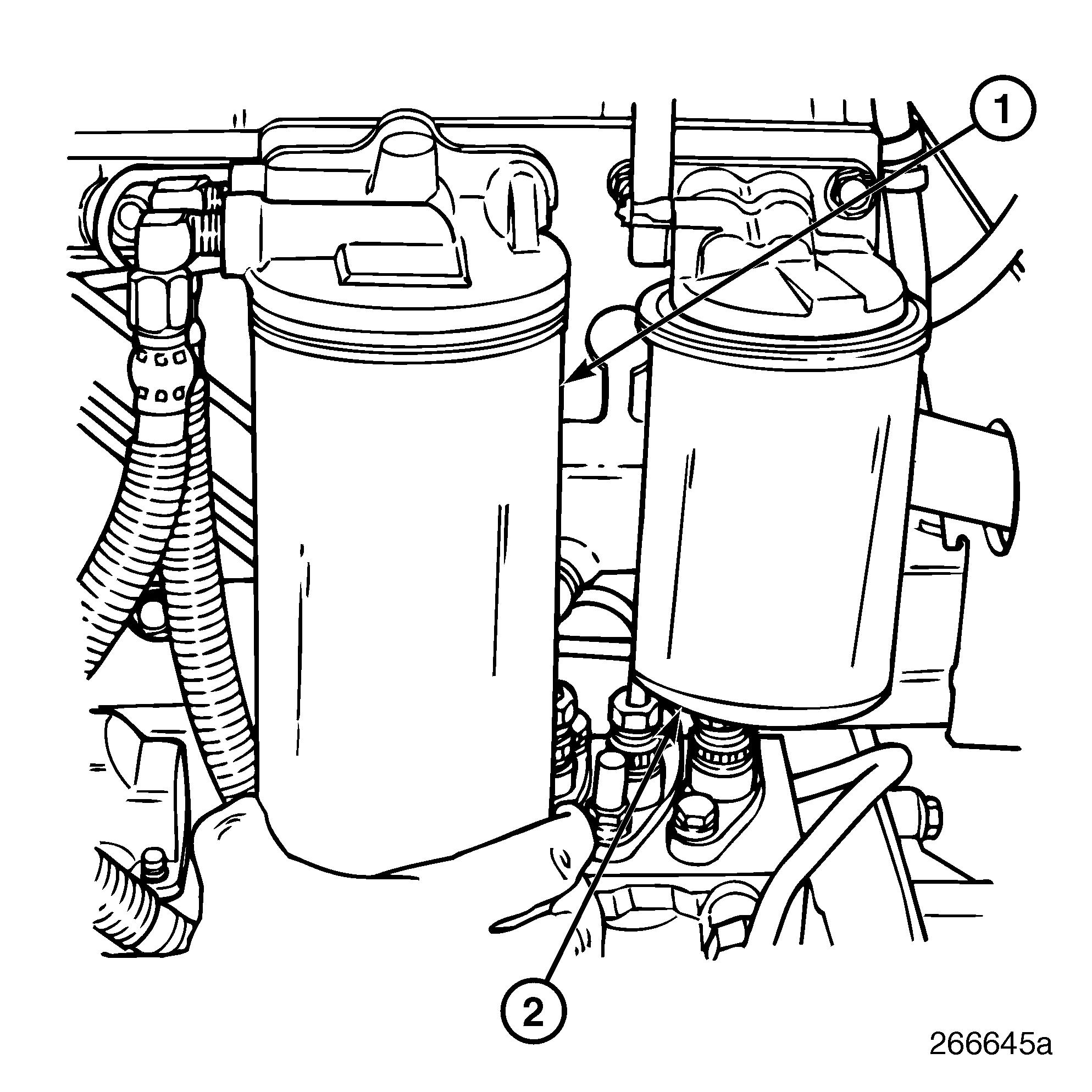
FUEL SECONDARY FILTER REPLACEMENT (ON ENGINE)
Replace the secondary fuel filter at every 150 hours of service.
1. Secondary Fuel Filter2. Coolant Conditioner (REF.)
1.Thoroughly wash the area around the fuel filter and mounting adapter mating area with a suitable solvent and blow dry the area with compressed air.
2.With the engine shut down, place a suitable container under the filter and remove the used fuel filter using filter wrench J 24783. Dispose of the cartridge in an environmentally responsible manner according to state and/or federal (EPA) recommendations.
Maintenance
Install secondary fuel filter using the following procedure.
1.Wipe the filter mounting base clean.
2.Apply a film of clean engine oil to the sealing gasket.
3.Fill the filter with clean fuel.
General field practice is to prime the fuel filters before installation. This practice can allow dirt to enter the outlet port of the filter if caution is not used. Use filtered fuel only when priming the filter. Prime through the series of small holes on the top of the filter. DO NOT prime the filter through the center hole.
4.Install the filter and tighten 3/4 to 1 turn after gasket contacts the base.
5.Start the engine and check for leaks.
Use of anything other than genuine MACK filters may cause damage and void the engine warranty. Change filters according to the recommended maintenance schedule.
FUEL LINES AND FLEXIBLE HOSES Pre-Start Inspection
Check hoses daily as part of the pre-start inspection. Examine hoses for leaks and check all fittings, clamps and ties carefully. Make sure that hoses are not resting on or touching shafts, couplings and heated surfaces including exhaust manifolds, any sharp edges or other obviously hazardous areas. Since all machinery vibrates and moves to a certain extent, clamps and ties can fatigue with age. To ensure continued proper support, inspect fasteners frequently and tighten or replace them as necessary.
Investigate leaks immediately to determine if fittings have loosened or cracked, or if hoses have ruptured or worn through. Take corrective action immediately. Leaks are not only potentially detrimental to machine operation, but they can also result in added expense caused by the need to replace lost fluids.
Personal injury and/or property damage may result from fire due to the leakage of flammable fluids such as fuel or lube oil.
Service Life
If the engine fails to start after installing new fuel filters, refer to Systems Check and Lubrication under Final Preparation and Operational Check.
Fuel Injectors
Due to the extremely high pressures necessary for the proper atomization for diesel fuel, proper maintenance, servicing and fuel quality should be maintained. At 3,000 hours of operation, the injectors should be inspected for proper opening pressures and spray patterns to ensure the proper combustion of fuel. All fuel injection servicing should be accomplished by a properly certified facility working in conjunction with MackPower™
A hose has a finite service life. With this in mind, all hoses should be thoroughly inspected at least every 500 operating hours (1,000 hours for fireresistant fuel and lubricating oil hoses) for indications of twisted, worn, crimped, brittle, cracked or leaking lines. Hoses with their outer cover worn through or damaged metal reinforcement should be considered unfit for further service.
All engine hoses should be replaced during major overhaul and/or after a maximum of 1,000 hours of service. Fire-resistant fuel and lube oil hose assemblies do not require automatic replacement after 1,000 hours or at major overhaul, but should be inspected thoroughly before being put back into service.


