3 minute read
REPAIR INSTRUCTIONS


159
Use a cleaning tank large enough to accommodate the largest component to be cleaned. Fill the tank with a suitable solvent and always use caution while cleaning parts. Parts may be dried with compressed air.
1.Scrape any remaining gasket material from the block.
2.Using a wire brush or rotary wheel, remove any rust, corrosion or other debris from the block.
3.Clean all other block surfaces with mineral spirits or other suitable solvent.
4.Using due care and caution, clean and dry the block with compressed air.
Inspection
A complete discussion of the proper methods of precision measuring and inspection is outside the scope of this manual. However, every shop should be equipped with standard gauges such as bore gauges, dial indicators, outside and inside micrometers, thickness gauges and straightedges.
Check the cylinder block for indications of cracking or coolant leakage. If any damage is suspected, use a standard dye penetrant or magnaflux procedure to determine if cracks exist. A cracked engine block must be replaced and never reused.
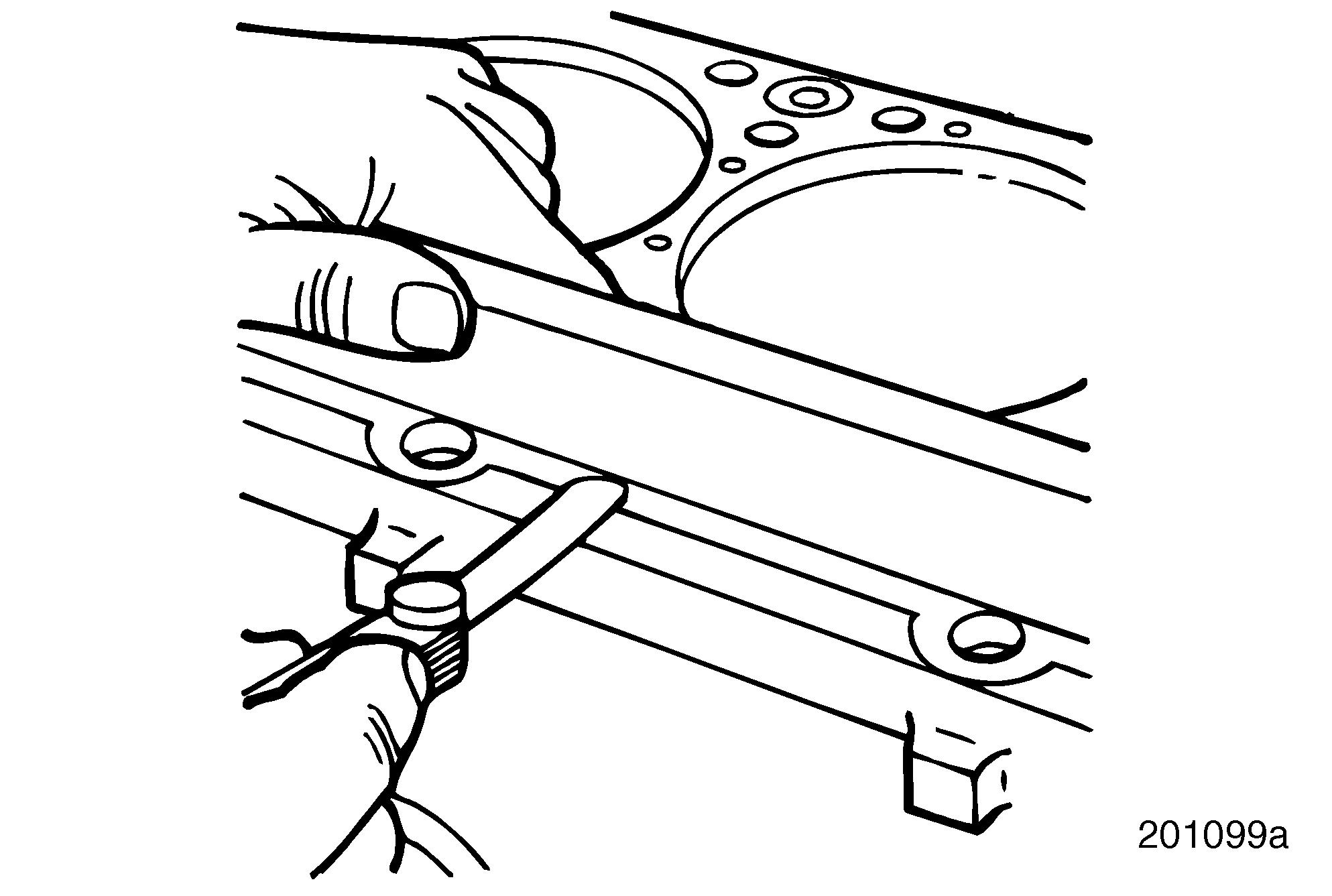
Refer to Figure 159.
Using a straightedge (PT5027, or equivalent) and thickness gauges, check the cylinder head mounting surfaces for flatness. The cylinder block mounting surface, on a service block, should be flat within 0.002 inch (0.051 mm) per head mounting.
If the cylinder block is determined to be serviceable after thorough cleaning and inspection, reassemble the engine. Use replacement or original parts, as determined during component inspection.
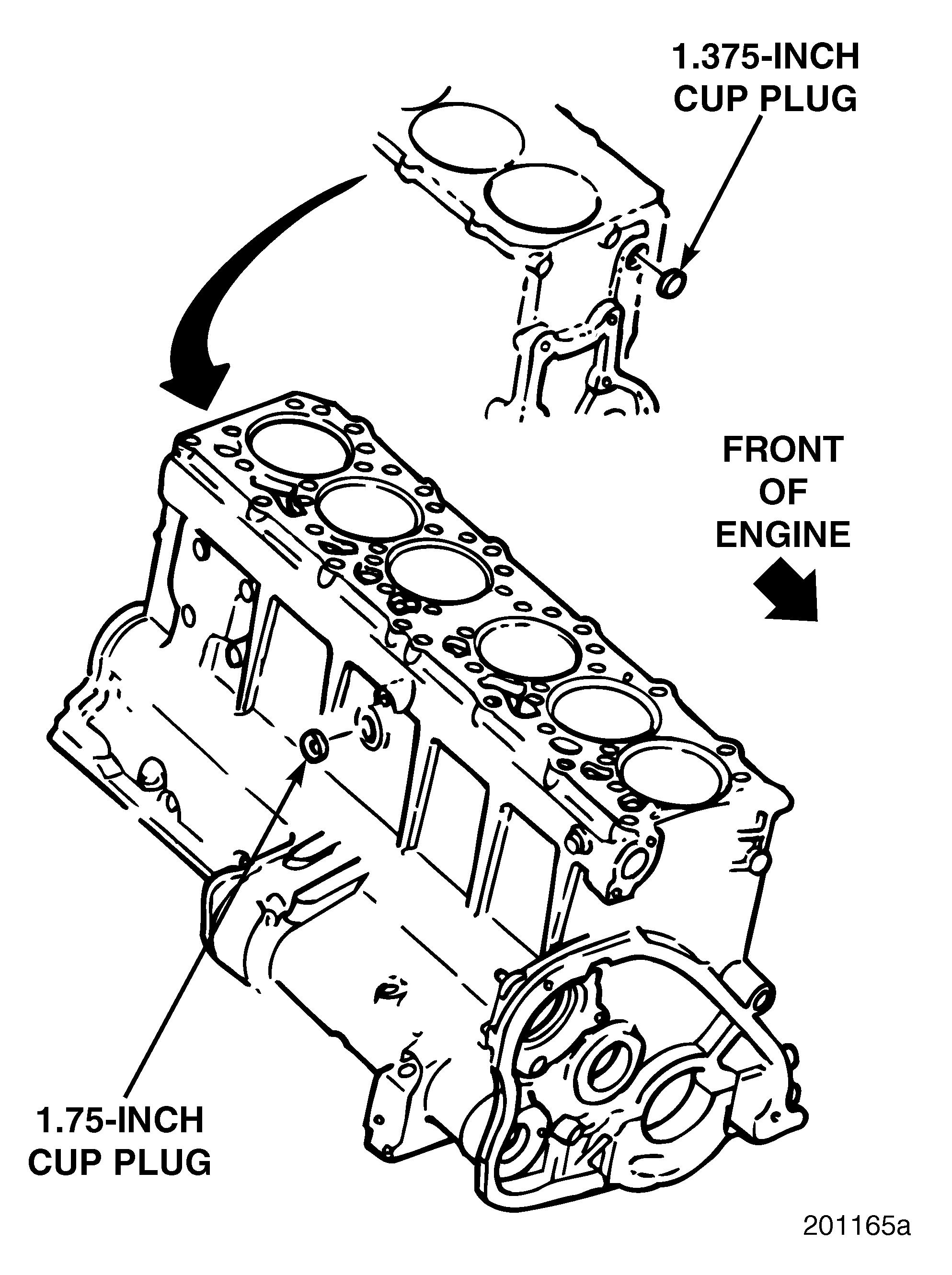
CORE PLUG REPLACEMENT Removal
Refer to Figure 160.
1.Using a hammer and punch, drive one edge of the plug inward. The plug should rotate causing the opposite edge to move outward. When the edge moves out far enough, grab it with a pair of pliers and pull it out.
If, after several taps with a hammer, the plug does not rotate and is being driven inward, stop tapping. Drill a hole approximately 1/8 inch (3.2 mm) in diameter in the center of the plug. Insert a sheet-metal screw in the hole. Leave enough of the screw protruding from the plug to allow a pry bar to be inserted under the head of the screw and pry the plug out.
Repair Instructions
2.Clean the plug hole(s) with a wire brush or wire wheel. After cleaning, visually check the surface for cracks. When satisfied that there are no cracks anywhere in the block, replace the plug(s).
160
161
Installation
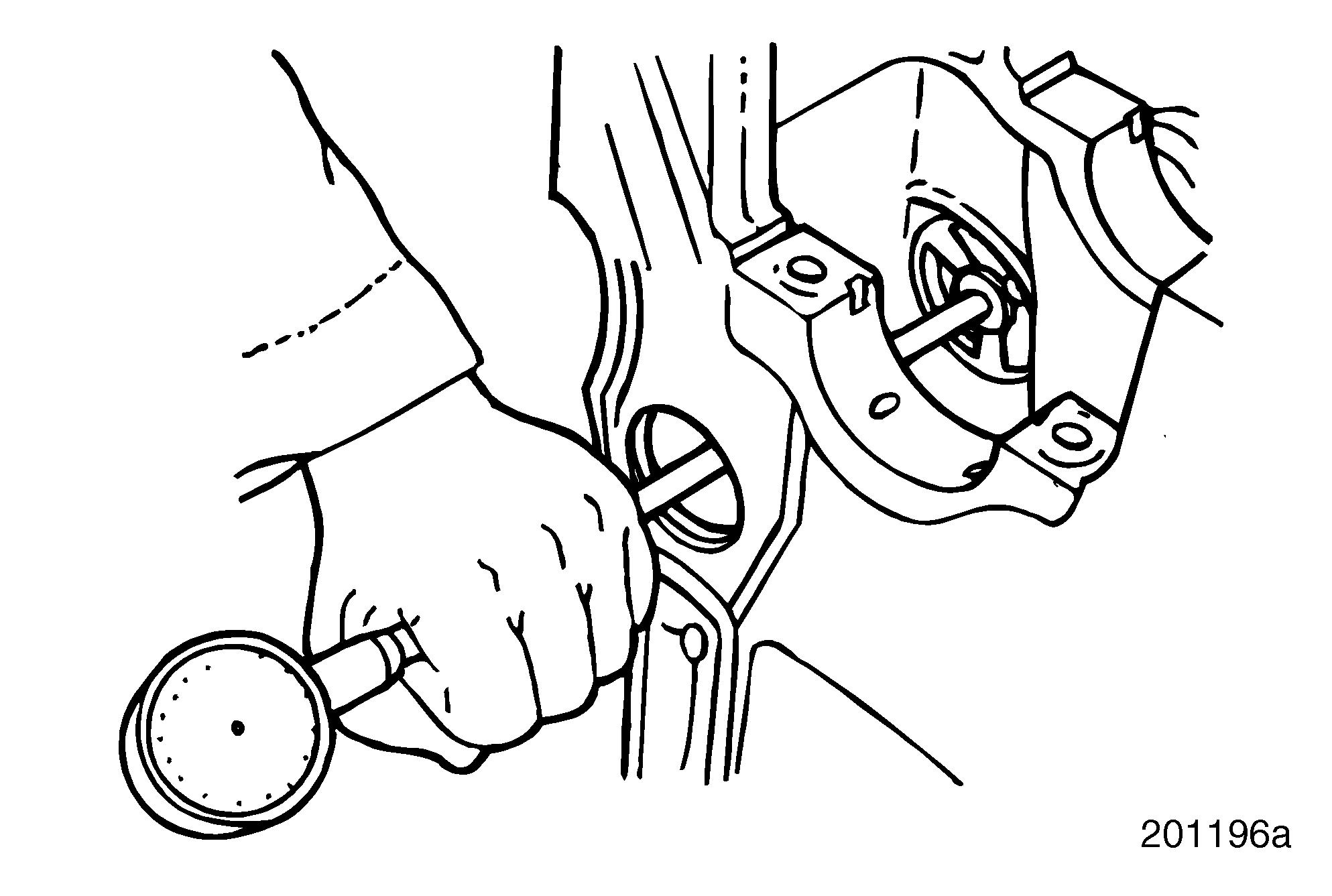
1.After cleaning the plug hole, apply a thin coat of Loctite® 277 to both the surface of the hole and the outer edge of the plug.
2.Using a proper driver, align the plug in the hole and drive it inward until the outer lip of the plug is flush with the cylinder block. Refer to Figure 161.

Any rust around a pipe plug is an indication of a leak and the plug should be replaced.
Removal
1.Using an appropriate wrench, remove the plug.
2.Clean the threads in the block by running a tap into the hole, just far enough to remove any rust on the threads without expanding the diameter of the hole. Use compressed air to remove any chips from the block.
It is best to replace a leaking pipe plug. However, if reusing the same plug, clean thoroughly, paying special attention to the threads.
3.Using a wire wheel, clean the threads of the plug. Visually check the thread surfaces for burrs or damage. Then clean and check the remaining surfaces.
New plugs already have a sealer applied to the threads. Applying a Teflon sealer to the threads will not adversely affect the precoating.
Repair Instructions
Installation
Apply appropriate Teflon thread sealant to the threads and install the plug. Torque to specification. Refer to the Torque Chart in the Specifications section.
When checking or assembling engine components, refer to “FITS AND LIMITS” on page 289 and “TORQUE SPECIFICATIONS” on page 295 for specified dimensions and torque settings.
CAMSHAFT BUSHINGS
Description
Lubrication oil is pumped into the cylinder block main oil gallery. Oil from the gallery flows to each main bearing bushing bore and then on to the respective camshaft bushing bore, providing lubrication for both the crankshaft and camshaft bushings. Camshaft bushing bores No. 1, 2 and 5 are grooved to supply oil to other components as well. Oil from the No. 1 camshaft bushing bore flows on through a drilled passage to lubricate the front auxiliary driveshaft bushing. Oil from the No. 2 and 5 camshaft bushing bores flows on through vertical drilled passages to lubricate the rocker arm assemblies. Oil from the No. 4 camshaft bushing bore flows through a cast groove in the cylinder block bushing bore to lubricate the fuel injection pump, the rear auxiliary driveshaft bushing and the raw water pump.
Inspection
During overhaul, check the inside diameter of the camshaft bushings. Replace camshaft bushings as required.
1.Using a telescope gauge or suitable inside micrometer, measure the ID of each camshaft bushing in the cylinder block. Record the dimensions. Refer to Figure 162.
2.Refer to “FITS AND LIMITS ” on page 289 for camshaft bushing measurement specifications. Compare the recorded dimensions with specifications.
3.If bore size exceeds tolerance or if there is any evidence of scratching or scoring, replace the bushings.
Removal
Refer to Figure 163.
Use camshaft bushing remover/installer kit
J 37713 (use with J 21428-01 kit) for camshaft bushing removal.
Camshaft bushings are identified in sequence from 1 to 7, starting from the front of the engine.
1.Using camshaft bushing remover/installer kit J 21428-01 (2), with the correct pilot adapter (J 37713 kit) and a hammer (3), remove the No. 1 camshaft bushing (4) from the cylinder block (1).
2.Remove the remaining six bushings in sequence.
Page 129
163


