
1 minute read
REPAIR INSTRUCTIONS


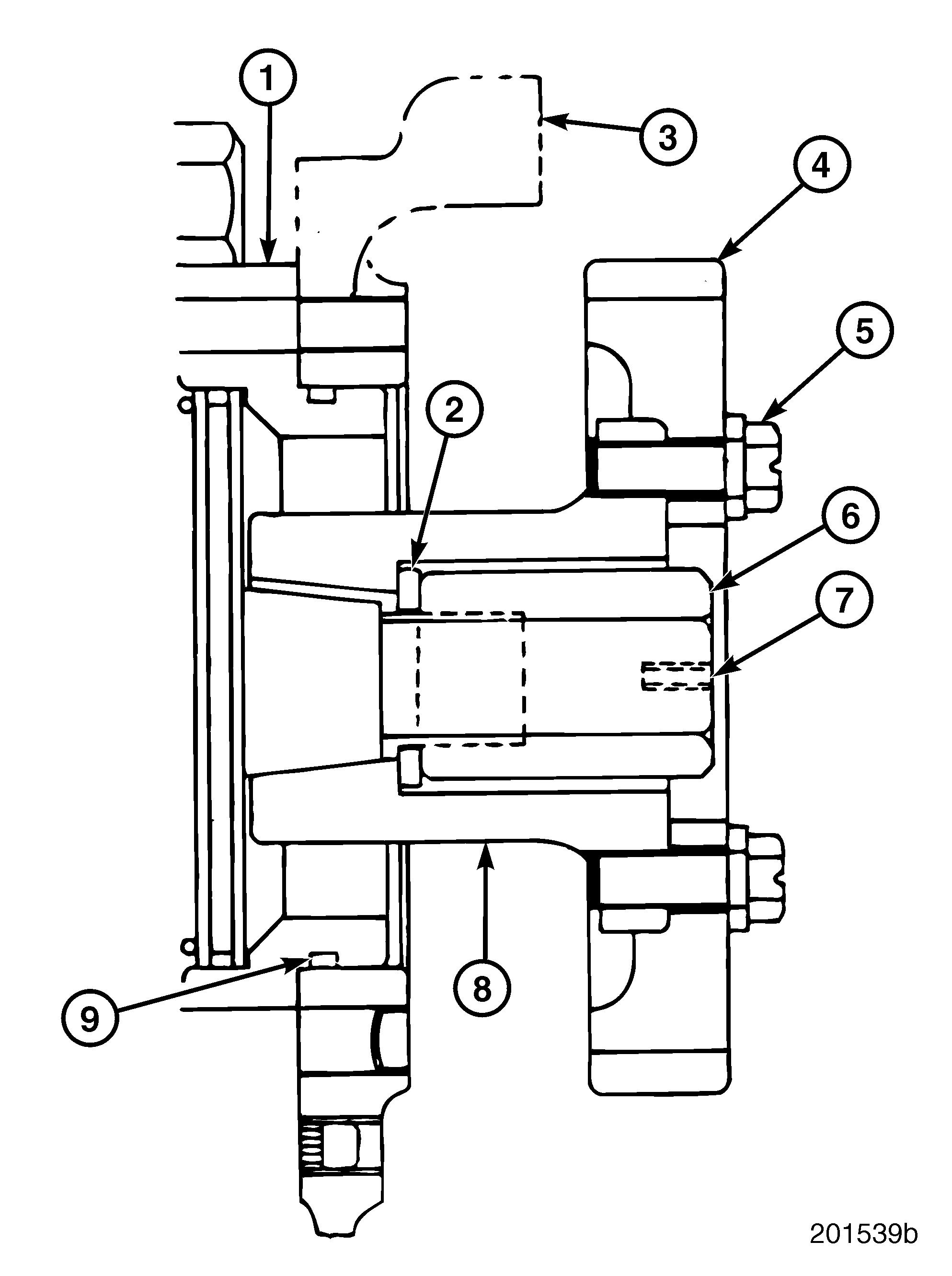
Water Pump Removal
Refer to Figure 133.
1.Remove the two capscrews (4) retaining the water pump bracket (5) to the cylinder head.
2.Remove the water pump capscrew (2) and lifting eye bracket to cylinder head screw (1) from lifting bracket (3). Remove water pump (9).
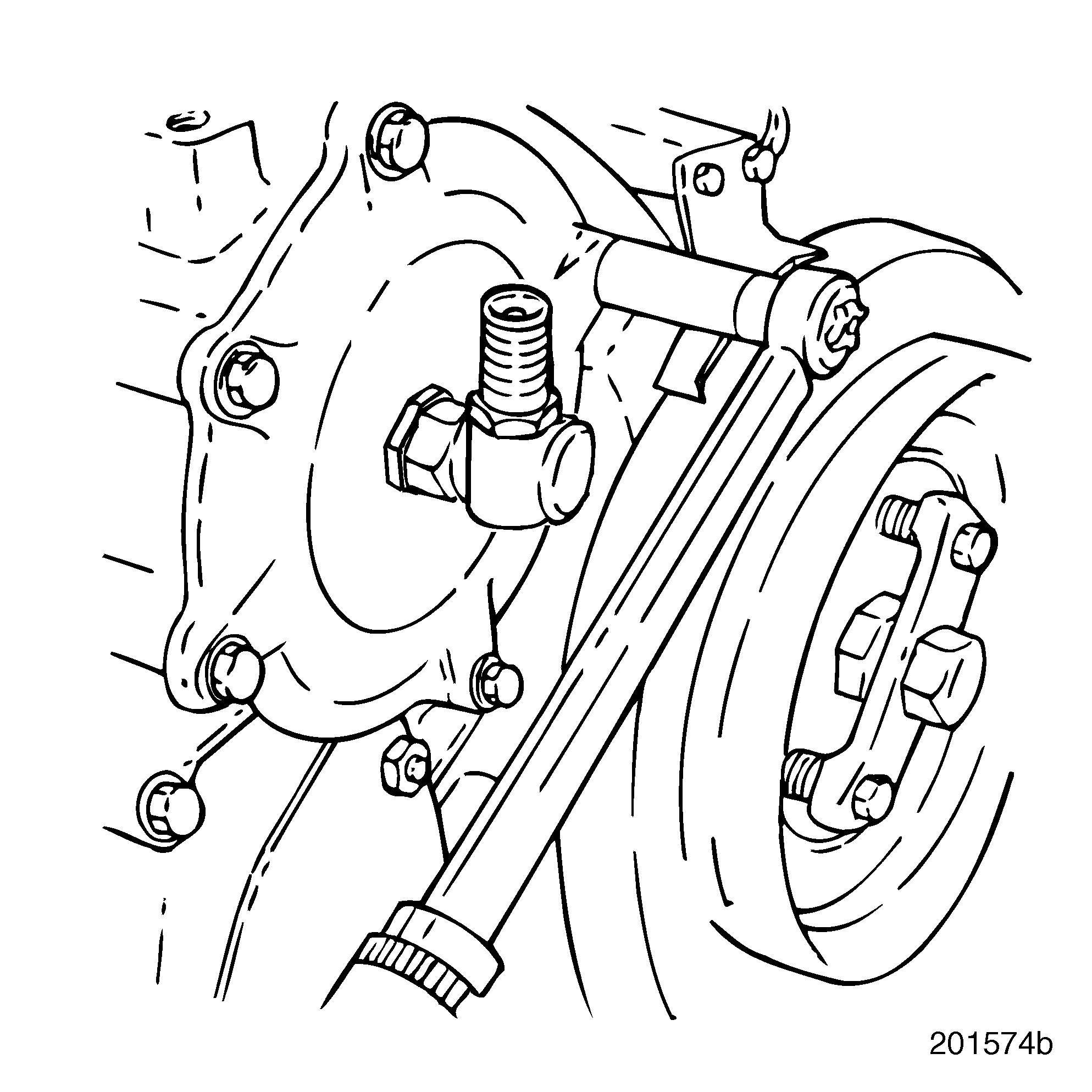
Fuel Injection Pump Removal
Anytime the injection pump is removed and reinstalled, it is necessary to set injection pumpto-engine timing. Refer to “Injection Pump FixedTiming Procedures” on page 273.
Refer to Figure 135.
1.Disconnect the throttle linkage from the injection pump.
2.Disconnect LDA hose and fuel return line and fuel and oil supply lines from injection pump.
If the fuel injection pump does not require servicing, set injection pump-to-engine timing before removal. This allows ease of installation. Refer to “Injection Pump Fixed-Timing Procedures” on page 273.
3.Working from the front of the engine, remove the injection pump driven gear access cover capscrews.
4.Remove the access cover and mechanical tachometer drive as an assembly.
1. Capscrew (Retains Bracket to Cylinder Head)
2. Capscrew (Retains Bracket and Water Pump)
3. Engine Front Lifting Bracket
4.
5.Water
6.Capscrew
5.Remove four capscrews (5) securing the injection pump driven gear (4) to the hub (8).
6.Remove the injection pump driven gear (4).
7.Remove the four injection pump mounting capscrews.
8.Remove injection pump by moving it away from mounting flange. Grasp firmly, lifting the back of the pump slightly, using a smooth motion to disengage the pump from the engine block.
Repair Instructions
Valve Cover Removal
Refer to Figure 136.
1.Remove all remaining capscrews (2) securing the two valve covers (1).
2.Remove valve covers (1).
3.Inspect valve cover gaskets and replace if damaged or covers indicate leakage.
Injector Nozzle Holder Removal
SPECIAL TOOL REQUIRED r Injection Nozzle Puller J 37093
After removing the nozzles, it is a good practice to label or tag them for reinstallation into the same cylinders. After removal, place nozzles on a clean surface.
Refer to Figure 137.
1.Remove nozzle holder retainer (2).
2.Assemble injection nozzle puller J 37093 as follows: a.Attach nut (12), bearing (11), spacer (10) and rubber washer (9) to tool handle (1). b.Screw handle (1) in threaded hole of nozzle holder (5) until rubber washer (9) is slightly compressed.
3.With tool in position, turn nut (12) clockwise to draw nozzle holder from cylinder head nozzle mounting hole (8).
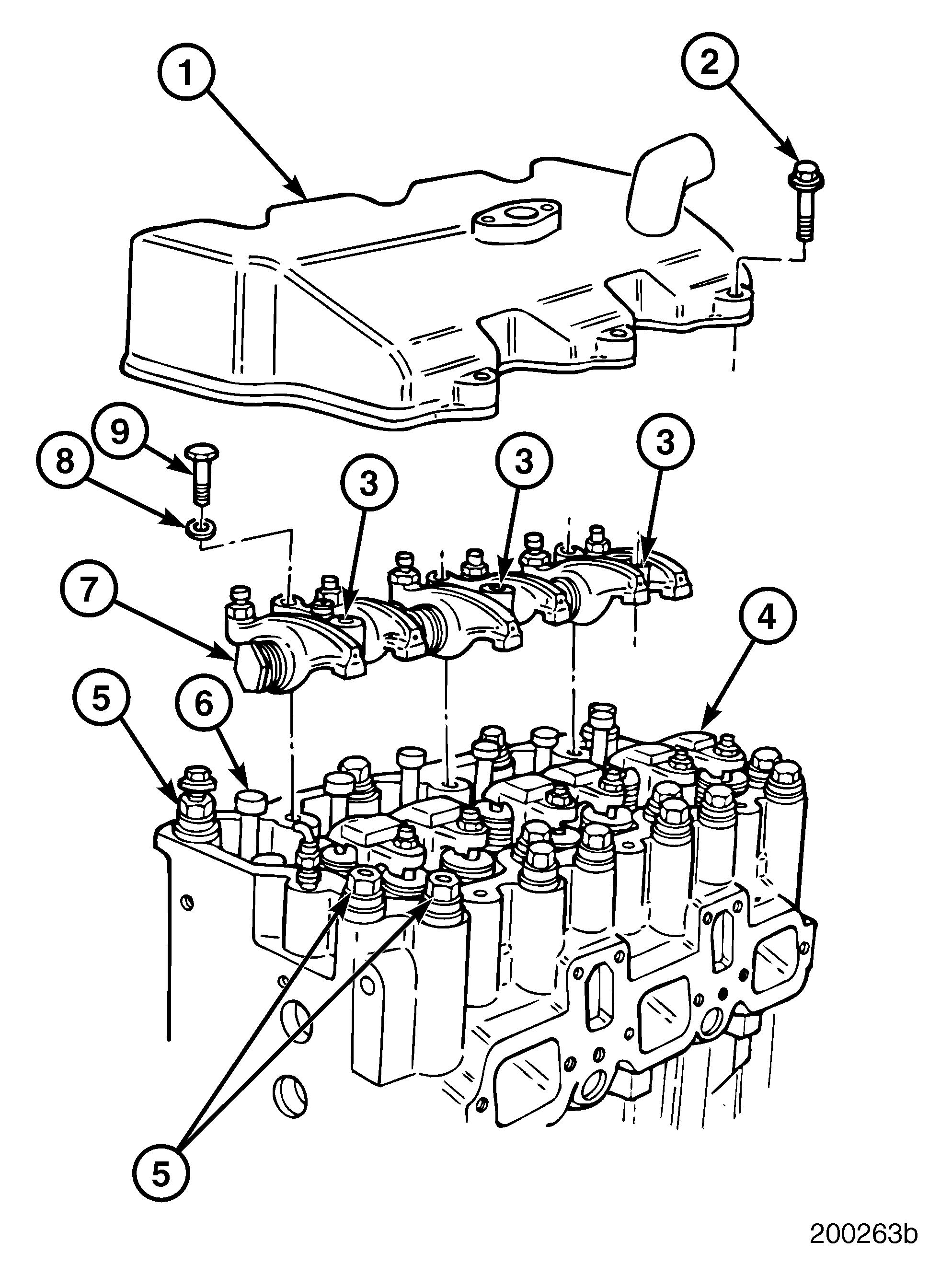
4.Continue turning nut until nozzle holder is free of insert. Remove nozzle holder and puller tool as an assembly.
5.Remove nozzle holder gasket (7). The gasket is manufactured from a special iron material 0.060 inch (1.524 mm) thick.
6.Remove remaining nozzle holders in the same manner.


