2 minute read
REPAIR INSTRUCTIONS


24.From drive end of bearing housing, push oil seal (4) into seal bore with lip pointing toward drive end of housing. A light coat of oil may be used to ease installation.
25.Pushing on inner race of bearing, press bearings (17) onto shaft.
26.Pushing on outer race of bearing, install bearing and shaft sub-assembly into bearing housing.
27.Install the bearing retaining ring (19) in the bearing housing, ensuring it is securely seated in the retaining ring groove
28.Install slinger O-ring (5) on shaft near bearing housing.
29.Lubricate ceramic seal seat boot with WATER ONLY and press into seal bore of pump body. Exposed ceramic surface should face toward impeller bore.
It is extremely important that the seal components do not become soiled during assembly.
Repair Instructions
30.Slide pump body (with seal seat installed) over shaft, taking care not to dislodge seal seat as body is moved toward (and aligned with) bearing housing. Attach pump body to bearing housing with four 5/16″ bolts and lock washers.
31.Install carbon portion of seal with tensioning spring and spring washer over shaft and locate in seal bore with carbon face against ceramic seal seat. Slide seal retaining ring over shaft against seal thrust ring and locate in retaining ring groove.
32.Install inner wearplate (14) in pump body aligning notch in wearplate with pin in body.
33.Lubricate body with a film of water pump grease and aligning hole in top of cam/liner (8) with pin in pump body (7). Push into body until it is recessed about 1/8″ from end cover surface
34.Liberally grease the inside of cam/liner with water pump grease.
35.Install impeller O-ring in groove in impeller insert. Inserting end of impeller (12) with O-ring first, rotate impeller in direction of pump rotation to bend blades under cam and push into bore until impeller insert flats align with shaft flats. Then push impeller all the way into impeller bore. End of impeller should be approximately even with cam/ liner. Install rubber spline plug into end of impeller.
36.Install outer wearplate ensuring that notch in wearplate aligns with hole in top cam/liner.
37.Place a new end cover gasket (11) over pin in end cover. Install end cover aligning pin with hole in cam/liner.
38.Reinstall the impeller end cover (10) onto the raw water pump and insert the six special brass capscrews (9). Tighten the capscrews to specifications.
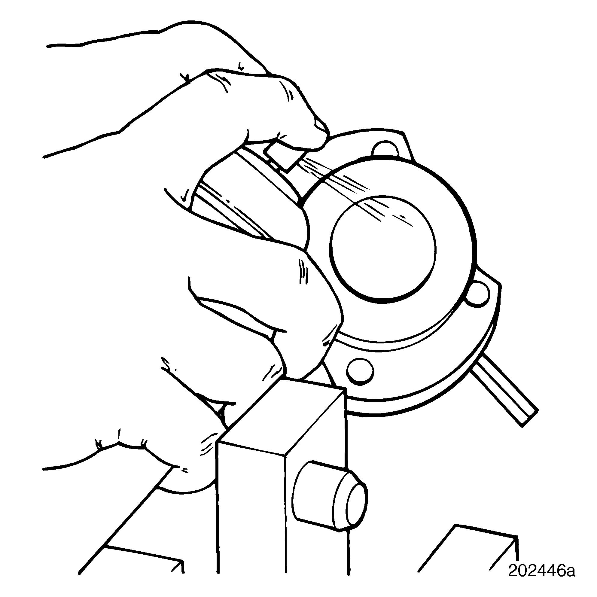
39.Install the coupling gear spacer and position gasket on the shaft end of the raw water pump housing. Using a hammer, tap Woodruf key into groove of shaft.
Gasket must be installed before coupling gear as the hole in the gasket is too small to fit over the gear.
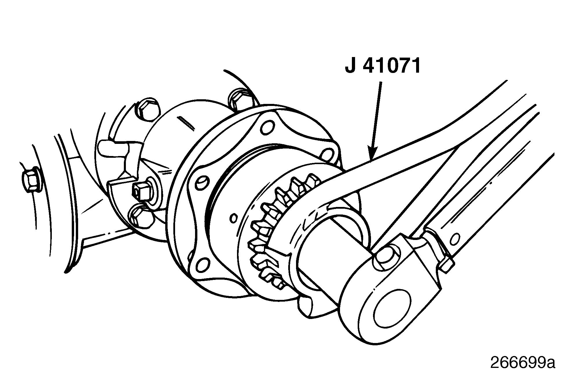
40.Position the coupling gear onto the end of the raw water pump shaft over the previously installed spacer. Heat the raw water pump coupling gear prior to installing it on the pump shaft.
Heat the metal portion of the coupling gear only and temperature is not to exceed 250°F. An alternative to heating the coupling gear is to remove the end cover (10) of the pump and impeller (12). Brace the shaft (18) and install the coupling gear by gently tapping it onto the shaft with a small mallet.
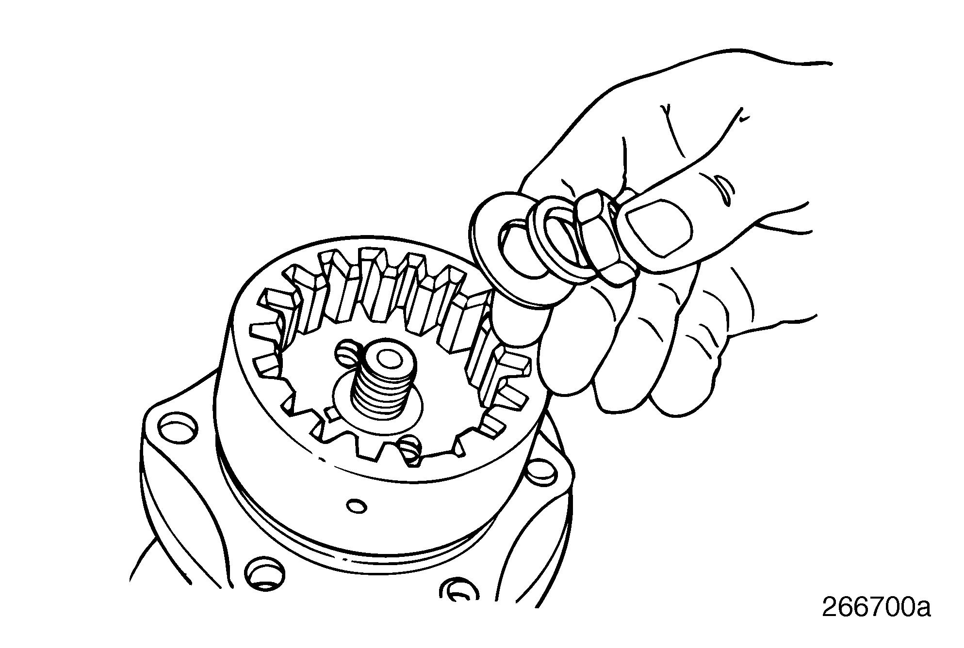
41.Install in order, flat washer, lock washer and nut onto the raw water pump shaft.
44.Refer
Repair Instructions
Fuel System Components Inspection
Injection Pump Drive Hub
DESCRIPTION
For mechanically governed engines, a scallopedtype drive hub is installed directly on the fuel injection pump the
SPECIAL TOOL REQUIRED r Pump Holding Fixture J 37078
CLEANING
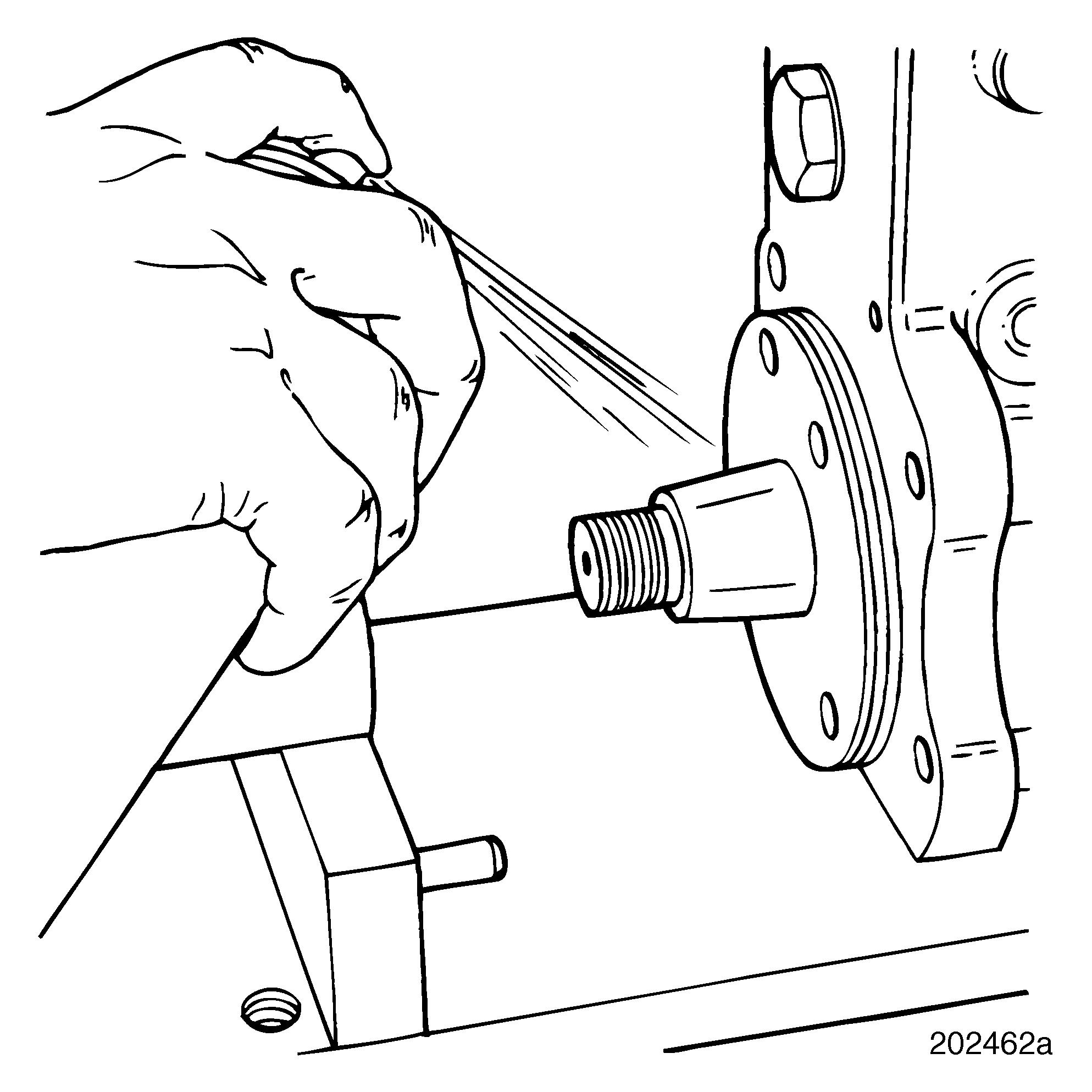
Degrease tapered surfaces of injection pump camshaft and drive hub with Stoddard No. 303 or Loctite 75559, or an equivalent degreasing agent.
Failure to degrease drive components prior to assembly may result in drive hub slippage.
258
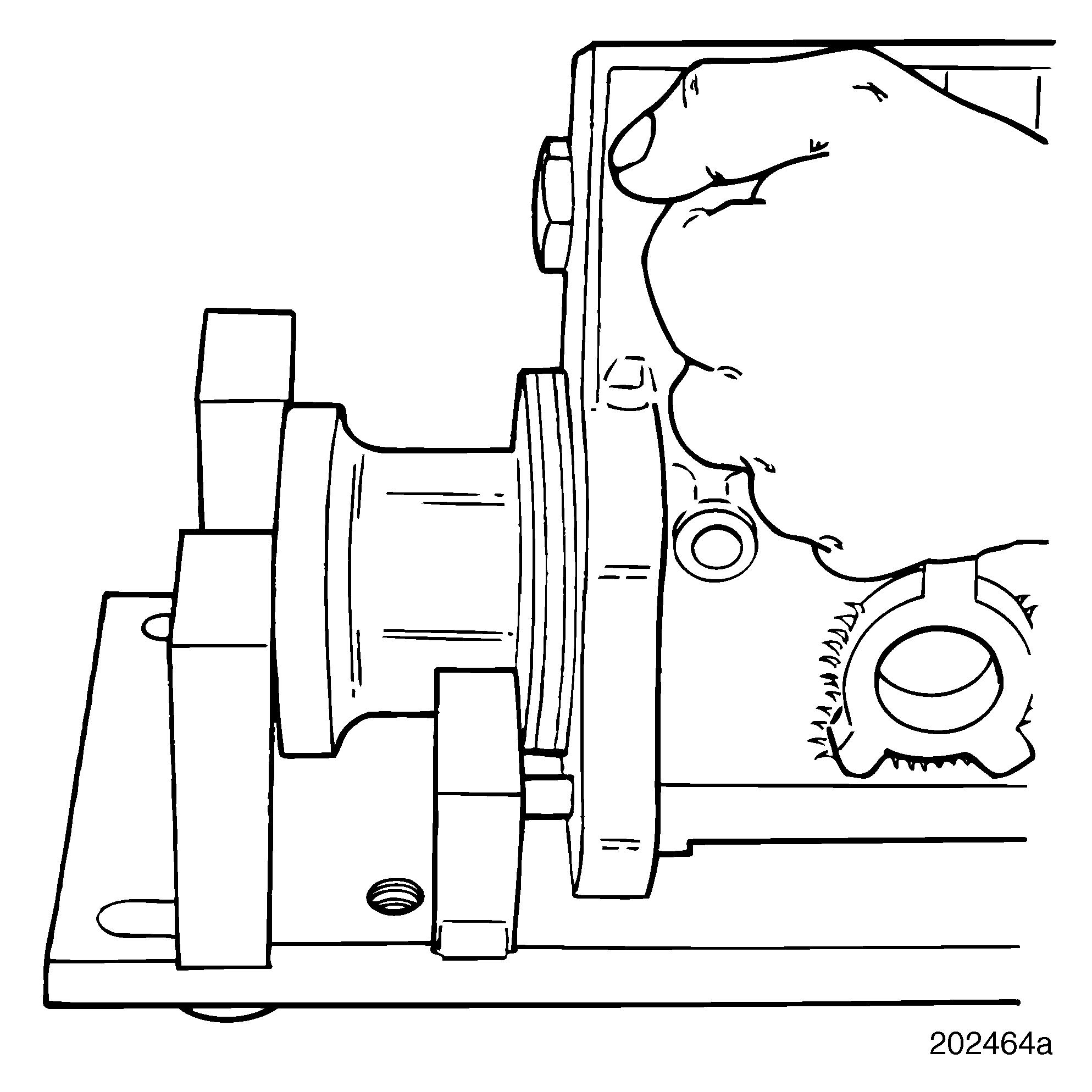
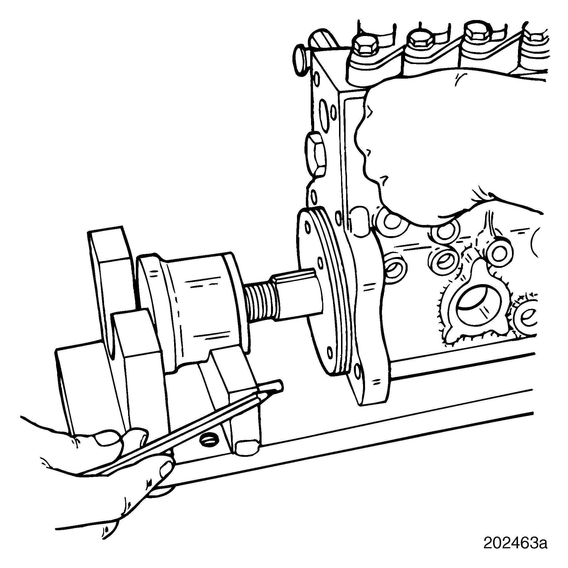
INSTALLATION
2.Place injection pump into pump holding fixture J 37078. Turn pump drive hub to allow pump to be slid forward, engaging alignment pins until pump mounting surface is flush with fixture