2 minute read
REPAIR


Inspection
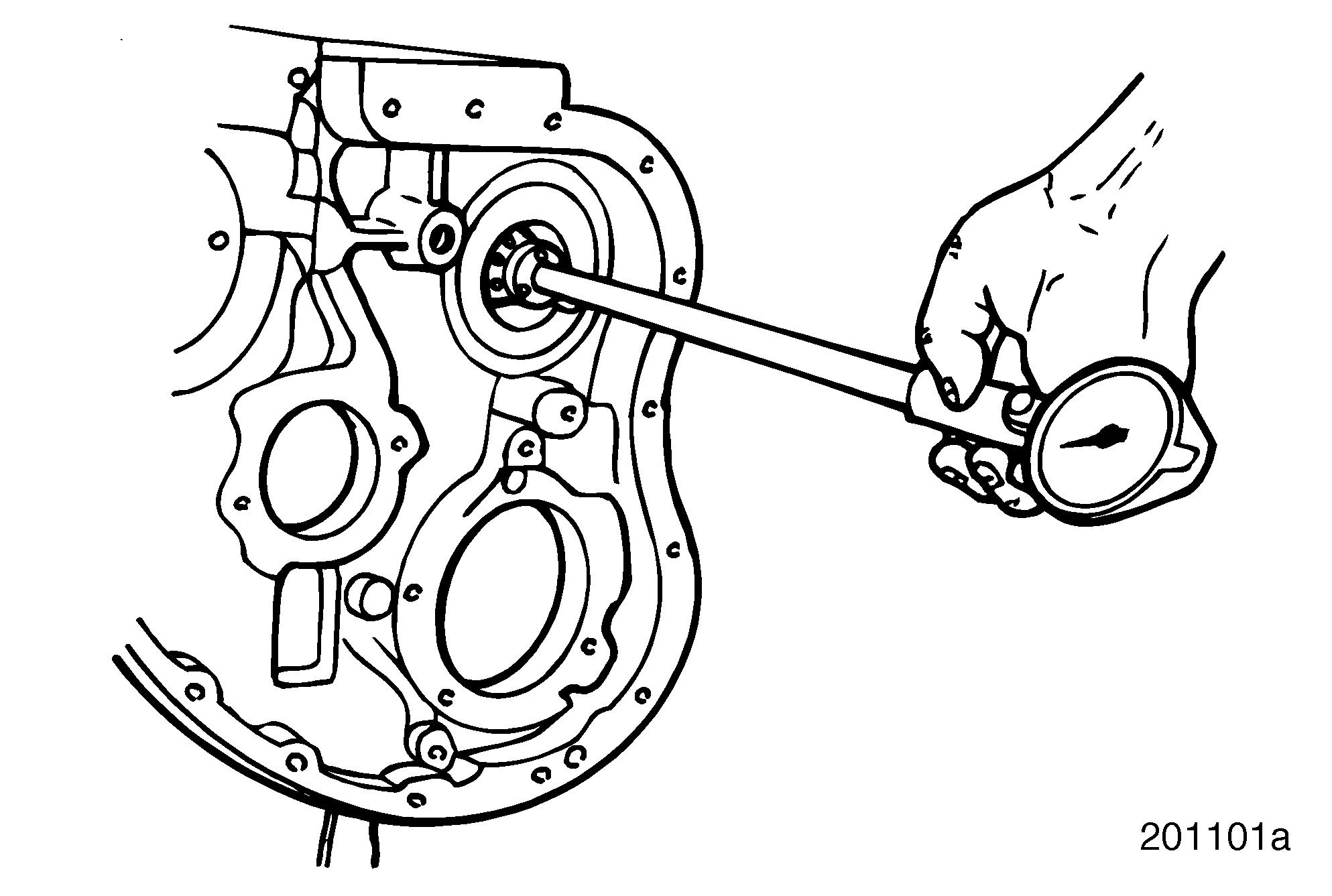
1.Using a telescope gauge or inside micrometer, measure the auxiliary bushing bores. Take two readings, perpendicular to each other, in each bore. Record the readings. Refer to Figure 168.
2.Compare readings with the tolerances listed in “FITS AND LIMITS” on page 289.
168
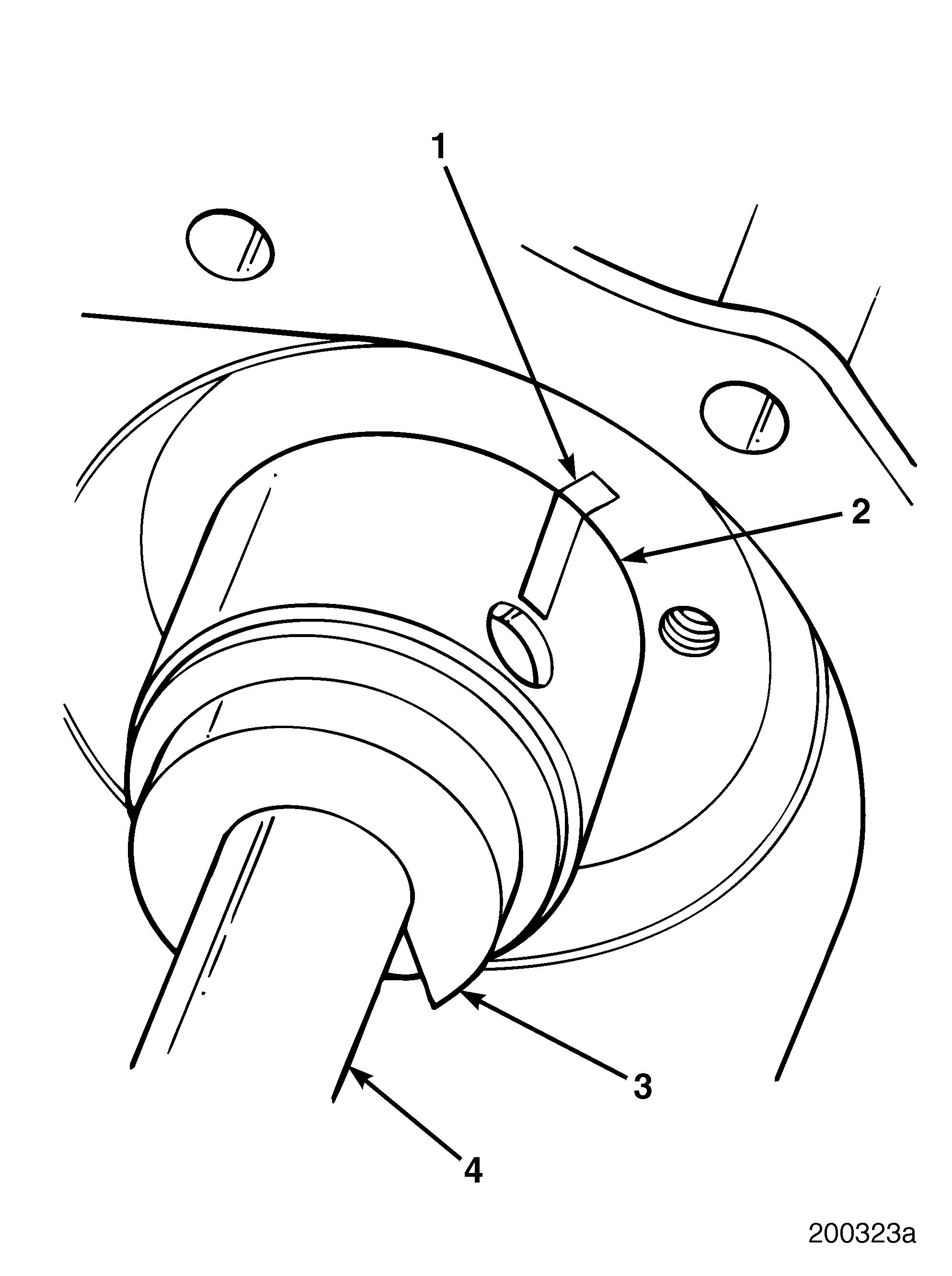
2.Using a dark-colored felt-tip marker, mark the block and the bushing with a line (1) to facilitate correct alignment during installation.
3.Clean the surfaces of the bushing and the bore. Dry both surfaces with compressed air.
4.Using camshaft bushing remover/installer kit J 21428-01 (4) and the appropriate pilot adapter J 37713 (3), install the bushing.
169
Installation
Correct installation of auxiliary driveshaft bushings is very important. If bushings are misaligned, lubrication oil will not be allowed to lubricate the auxiliary driveshaft journal. This will also cause the component lubricated through that journal to run without lubrication and prematurely fail.
If the oil feed hole in the oil metering plug at the rear of the auxiliary shaft is plugged up, the raw water pump may fail from oil starvation. Also, the loss of oil pressure that results from a missing plug can cause damage and problems in other components and parts. Make sure the plug is not missing or the metering oil hole is not plugged. If replacing the auxiliary driveshaft, make sure to install a new plug.
Refer to Figure 169.
1.Position a replacement bushing (2) against the side of the block at the rear bushing bore. Align the oil hole in the bushing with the hole in the block.
1. Alignment Mark
2. Bushing
3. Pilot Adapter J 37713
4. Camshaft Bushing Remover/Installer Kit J 21428-01
5.Check the bushing surface for burrs caused by installation.
Refer to “FITS AND LIMITS” on page 289 for correct bushing ID dimensions.
Repair Instructions
6.Using an inside micrometer or telescope gauge, measure the ID of the bushing to ensure against using an undersize bushing. An undersize bushing may cause the auxiliary driveshaft to seize in the bushing during installation.
The front auxiliary driveshaft bushing must be flush or recessed within 0.020 inch (0.508 mm) of the front of the cylinder block. Incorrect recess will cause misalignment of the oil supply hole, resulting in insufficient lubrication of the journal.
7.Working from the front of the cylinder block, repeat steps 1 through 6 to install the front bushing.
Cylinder Sleeve Installation
GENERAL INFORMATION
The cylinder sleeves are a wet-dry design made of centrifugally cast alloyed iron. Working with the pistons, piston rings, cylinder heads and cylinder head gaskets, the sleeves provide a seal against combustion pressure. The sleeves also transfer combustion heat to the engine coolant and guide piston travel. Correct extension of the sleeve flange above the top deck and uniform cylinder block counterbore is essential for satisfactory sleeve service life and head gasket seal.
Special Tools Required
r Depth Gauge J 26948 r Dial Bore Gauge J 5347-B r Cylinder Hone and Glaze Breaker J 5902-01
Installation Procedure
Refer to Figure 171.
1.Thoroughly clean and dry the prepared cylinder block (4), counterbore ledge (3) and cylinder sleeves (1). Refer to the cylinder block cleaning and inspection procedures in this section.
2.If the counterbore ledge (3) has been cut, place the shims (2) on the cylinder block counterbore ledge. Use the fewest number of shims required to achieve the proper cylinder sleeve flange height. Always place the thickest shim on the bottom.
If shims are used, apply RTV silicone on top of the shims only. If RTV is applied under the shims, the shims may be displaced when the sleeve is installed
3.Apply approximately a 0.120–0.160-inch (3.048–4.064-mm) bead of RTV silicone (Dow Corning Silastic RTV832) on the cylinder block sleeve seat and completely around the cylinder wall as shown in Figure 170. Do not use excessive amounts of RTV. Do not apply more than a 0.160-inch bead.


