2 minute read
REPAIR INSTRUCTIONS


10.Make sure the connecting rod is aligned with the crankshaft journal.
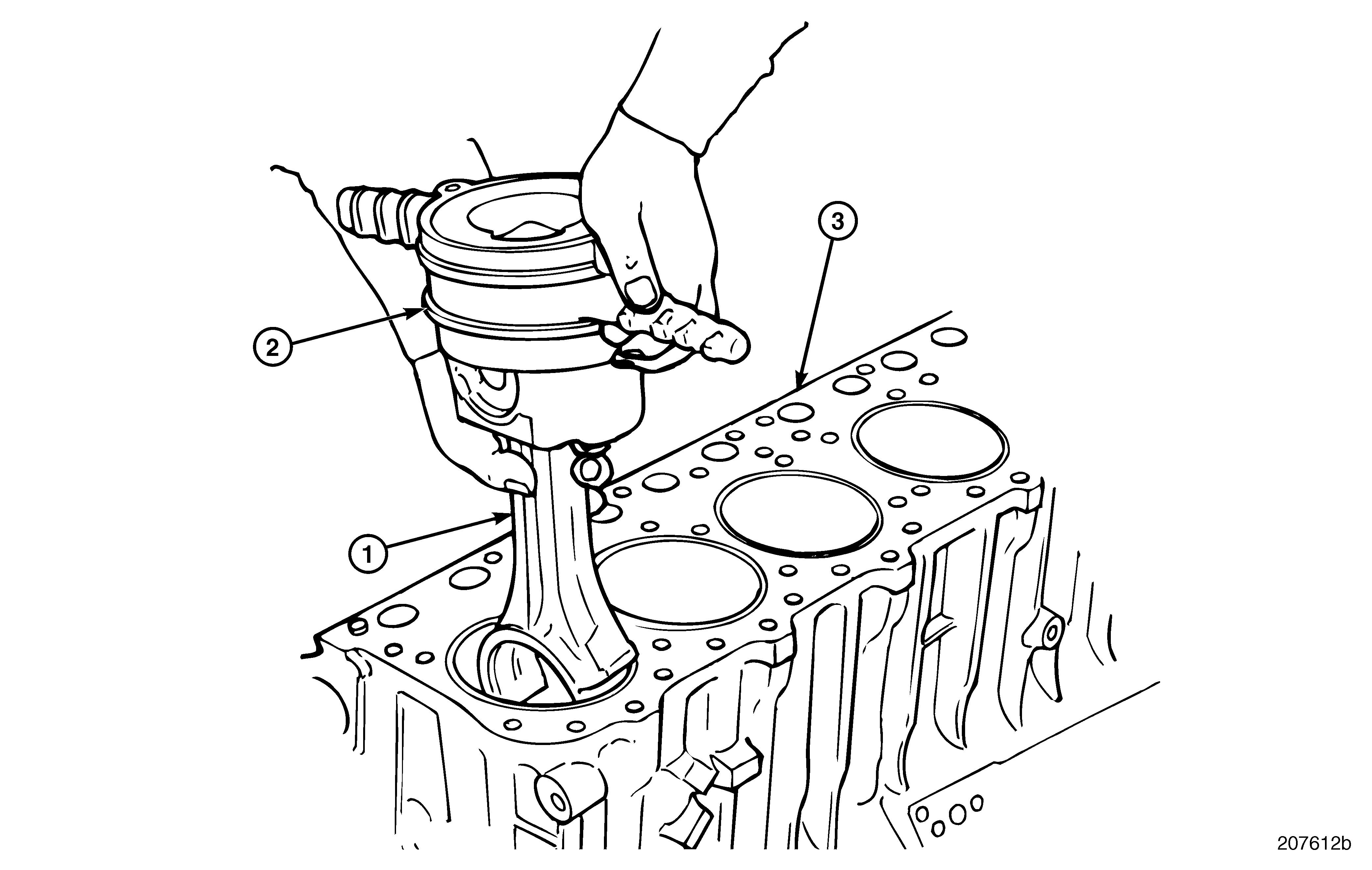
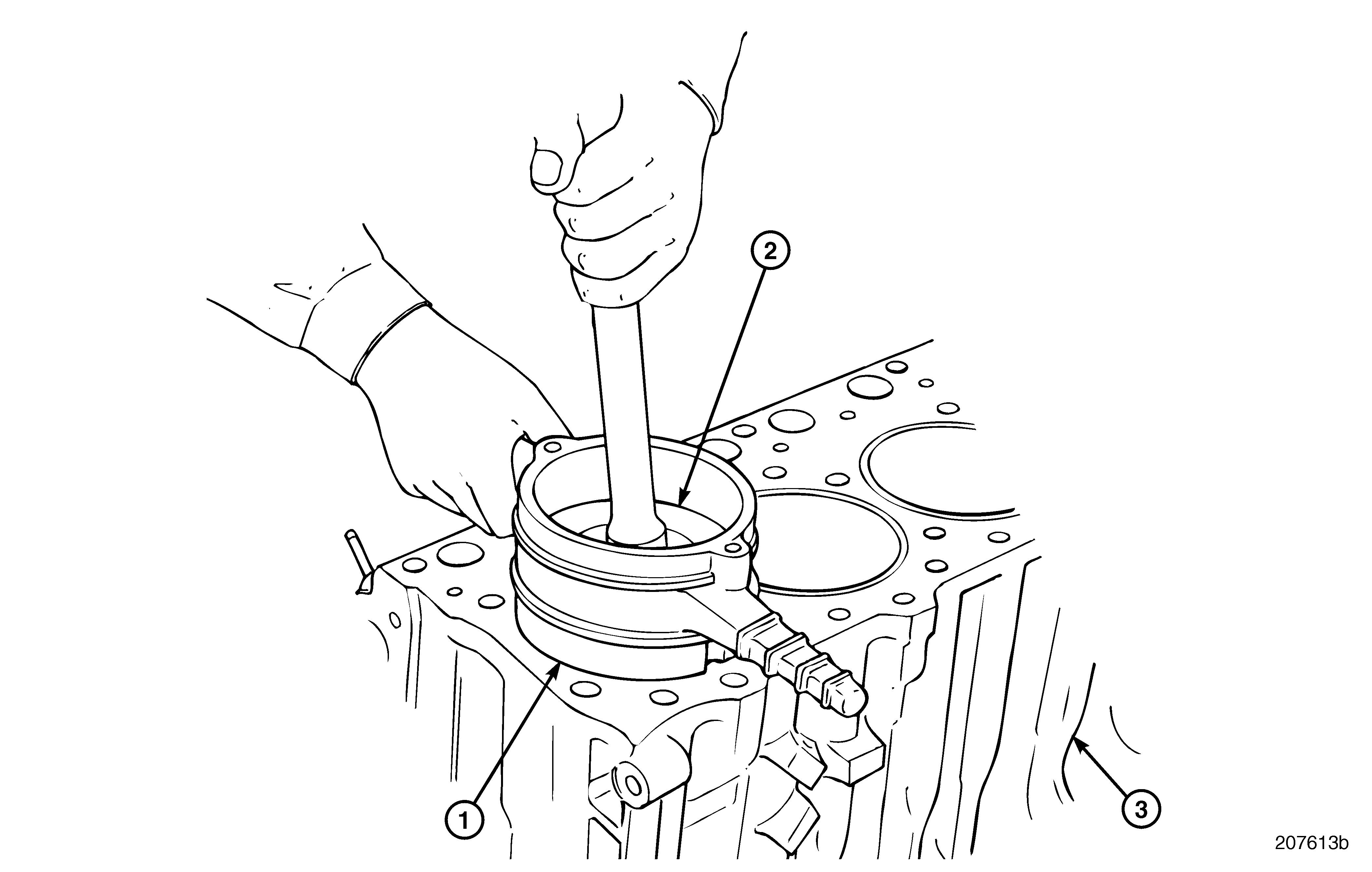
11.While applying downward pressure to the ring compression tool (1) to keep it in contact with the cylinder sleeve as shown in Figure 277, use a hammer handle to push the piston (2) through the tool. Continue pushing on the piston until the top ring has passed into the cylinder sleeve.
Do not force the piston. This indicates an incorrectly aligned ring. Remove the piston assembly, correct the problem, and then reinstall it. Make sure the compressor tool remains in contact with the cylinder sleeve until the piston clears the tool. If contact is not maintained, damage to the rings may result.
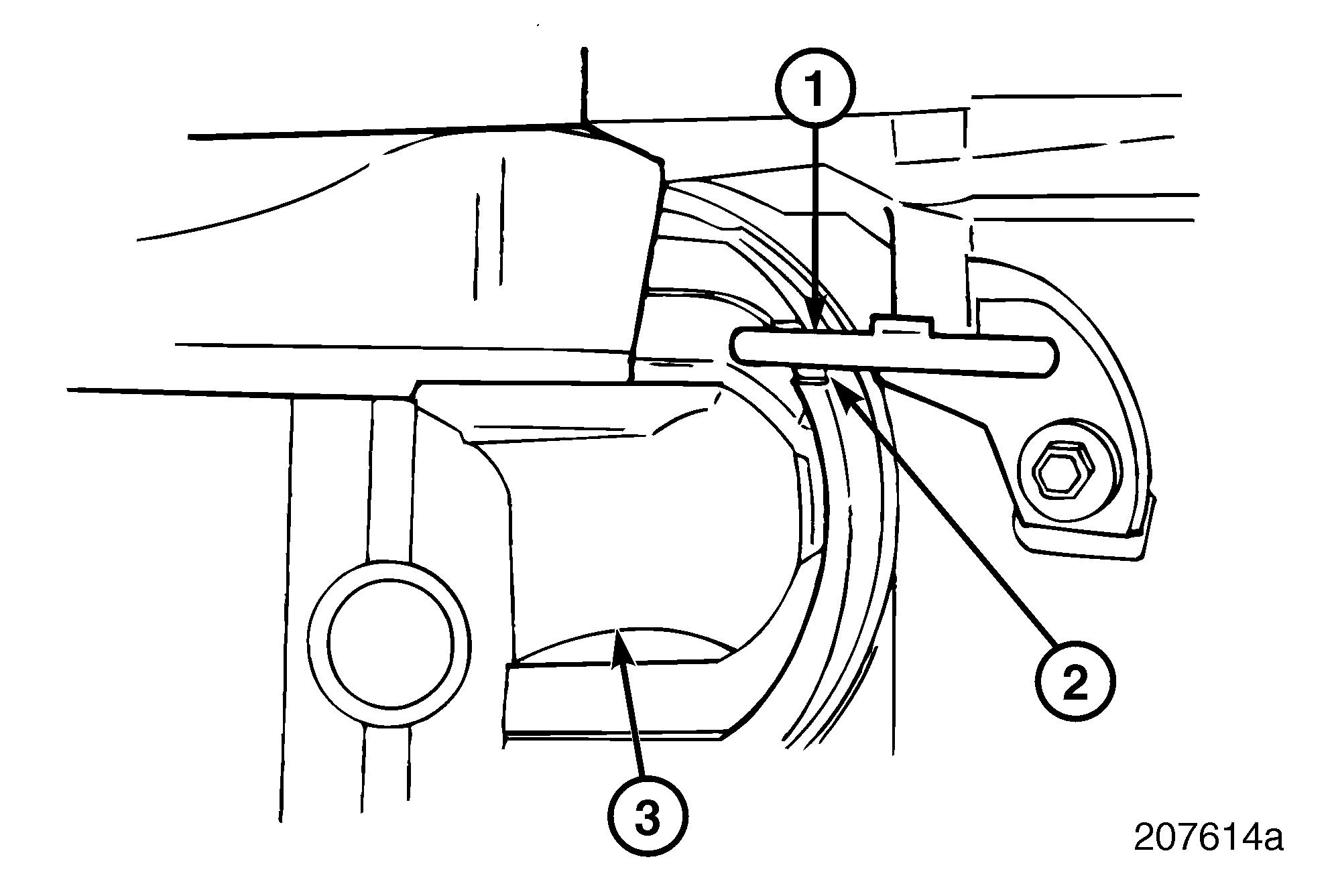
Before pushing the piston all the way down in the sleeve, check to see if piston cooling nozzle (1) is aligned with the nozzle clearance notch (2) provided in the lower end of the piston skirt as shown in Figure 278. Damage to piston or spray nozzle may result if it is not aligned.
Repair Instructions
12.Align the rod with the crankshaft journal and continue pushing the piston into the sleeve while guiding the rod end to clear the piston cooling nozzle and seat properly on the crankshaft journal.
13.Ensure that the correct rod bearing lower insert (matched to upper insert) and the alignment sleeves are positioned in the bearing cap.
14.Begin by installing the bearing cap at the No. 1 connecting rod journal (Figure 279) and check Running Clearance following the procedure later in this section. Repeat the running clearance check following the installation of each of the remaining five pistons.
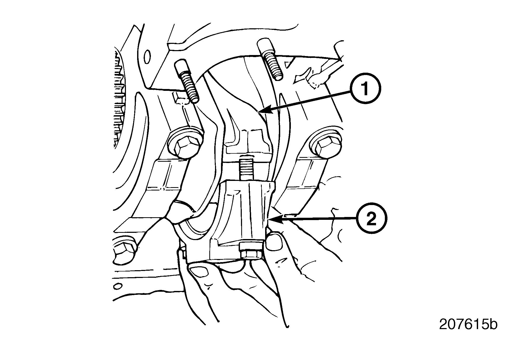
Running clearance must be checked after installing each piston. Damage to engine may result if clearance is not within specification.
To provide strict control of capscrew torque and ensure that optimum clamp load is obtained, an angle torque value has been established for the 14 mm full threaded capscrew. Torque value for the connecting rod capscrew is as follows: r 30 lb-ft (41 N•m) plus 90 degrees Special tool part No. BT91104, Torque Angle Gauge Set, is required to accurately torque the connecting rod bolts.
279
15.Repeat the above steps to install the No. 6 piston.
16.Rotate the crankshaft so that the journals for the No. 2 and No. 5 cylinders are at bottom dead center and install the No. 2 and No. 5 pistons following the above steps.
17.Rotate the crankshaft so that the journals for the No. 3 and No. 4 cylinders are at bottom dead center and install the No. 3 and No. 4 pistons, again following the above steps.
Running Clearance Check
1.Place a section of Plastigage on the rod cap bearing and assemble cap to the rod.
2.Apply a light coat of oil on the threads of the rod cap capscrews and secure the cap.
3.Angle torque the capscrews to 30 lb-ft (41 N•m) plus 90 degrees using torque angle gauge set BT91104, or equivalent.
The angle-torque method applies for 14-mm capscrew part Nos. 396GC211M and 396GC212M with partial and full threaded shanks, respectively. Intermixing the partial and full threaded 14-mm capscrews on the same connecting rod is permissible.
4.Remove the capscrews and cap.
5.Check the width of the Plastigage on the removed cap using a Plastigage width chart. After measuring width, remove the Plastigage from the bearing.
6.If the clearance is not within specification, correct the clearance as required: r If the clearance is less than specified, check behind the bearing for dirt, chips or burrs which would prevent the bearing from seating properly. r If the bearing bores and inserts are clean and undamaged, replace the inserts with inserts sized to provide the specified clearance.
7.Reposition the cap on the journal. Lubricate capscrews with clean engine oil, install the capscrews and tighten to the specified torque, 30 lb-ft (41 N•m) plus 90 degrees using torque angle gauge set BT91104, or equivalent.


