2 minute read
REPAIR INSTRUCTIONS


Cylinder Block Dowel Pins
SPECIAL TOOL REQUIRED r Flywheel Housing/Timing Cover Locating Pin Driver J 37712
REMOVAL
If it is necessary to remove the timing cover or flywheel housing locating dowel pins, do so as follows:
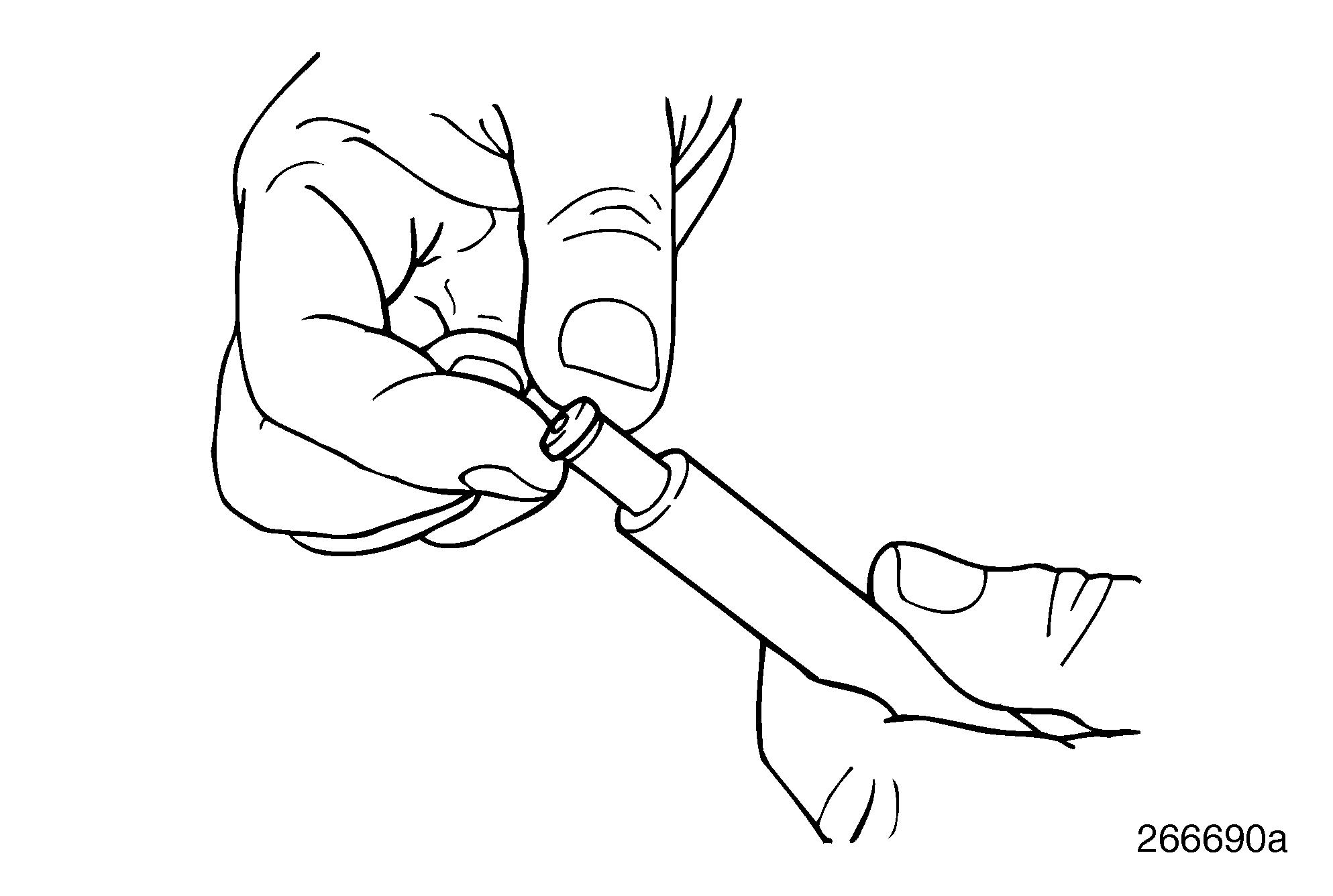
1.Securely clamp the pin with a pair of visegrip pliers.
2.While exerting an outward force, rotate pin back and forth until the pin works free from the hole.
INSTALLATION
Two precision-made dowel pins are used to locate the flywheel housing to the cylinder block. One dowel is round, the other is a blade type.
The dowels used for timing gear cover installation are similar except for the size. The smaller dowels are used for the timing cover. The larger dowels are used for the flywheel housing.
Round Dowel Pin Installation
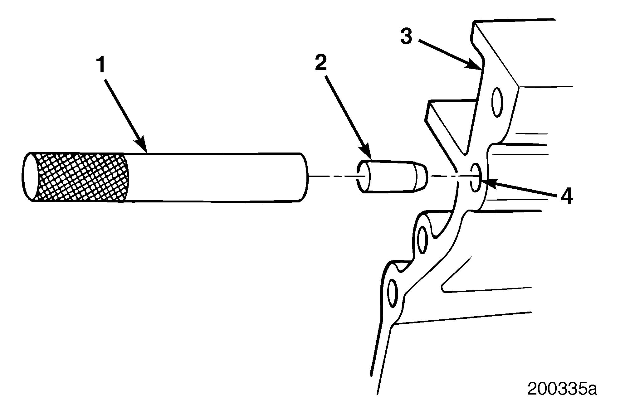
Refer to Figure 176.
1.Insert round dowel pin (2) into the flywheel housing/timing cover locating pin driver J 37712 (1).
2.Position exposed end of dowel into the left dowel pin hole in the rear face of the cylinder block and in the upper left dowel pin hole on the front face of cylinder block.
3.Using a hammer, drive the pin into the block until the driver contacts the cylinder block. When the driver has made contact with the block, the dowel pin will be at the correct dimension above the block.
Blade-Type Dowel Pin Installation
1.Position the round end of the blade-type dowel pin into the right dowel pin hole in the rear face of the cylinder block. The blade of this pin must be aligned vertically with the block.
2.Position the round end of the blade-type dowel pin into the lower right pin hole in the front face of the cylinder block. The blade of this pin must be positioned approximately 39 degrees outboard relative to the vertical center line of the block.
3.Using a hammer, drive the dowel pin into the block until the shoulder of the pin is flush with the cylinder block surface.
Page 139
Repair Instructions
AUXILIARY DRIVESHAFT AND CAMSHAFT INSPECTION
Auxiliary Driveshaft INSPECTION
1.Thoroughly clean auxiliary driveshaft.
2.Inspect auxiliary driveshaft journals and gear teeth for evidence of cracks, pitting, scoring or severe wear. If any of these conditions exist, replace the auxiliary driveshaft.
3.Inspect the rifle-drilled oil hole in the rear bushing area of the auxiliary driveshaft to make sure it is free and clear of debris or other contamination.
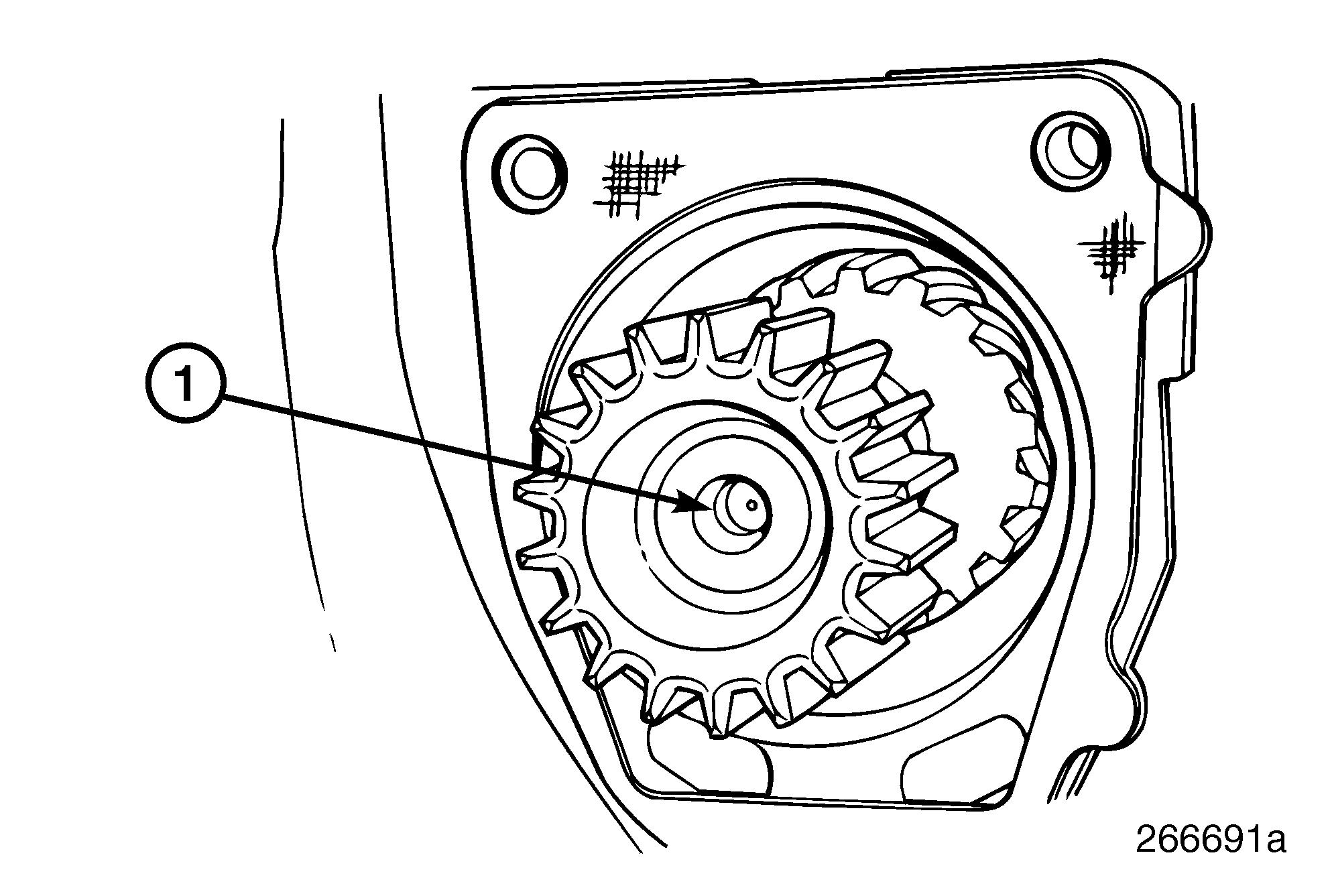
4.Inspect the rear end of the auxiliary driveshaft to make sure the oil metering plug is in place and that the metering oil hole in the plug is free and clear of debris or other contamination. If the plug is damaged in any way, or missing, replace or install a new plug.
If the oil feed hole in the oil metering plug at the rear of the auxiliary shaft is plugged up, the raw water pump may fail from oil starvation. Also, the loss of oil pressure that results from a missing plug can cause damage and problems in other components and parts. Make sure the plug is not missing or the metering oil hole is not plugged. If replacing the auxiliary driveshaft, make sure to install a new plug.
177
Auxiliary Shaft Oil Metering Plug Installation
Replacement of the oil metering plug is not normally necessary unless the auxiliary shaft requires replacement. When installing a new auxiliary shaft for the Marine M-E7 engine, an oil metering plug must be installed as outlined in the next steps.
1.Apply Loctite® 277, or equivalent, to the outer surface of the oil metering cup plug.
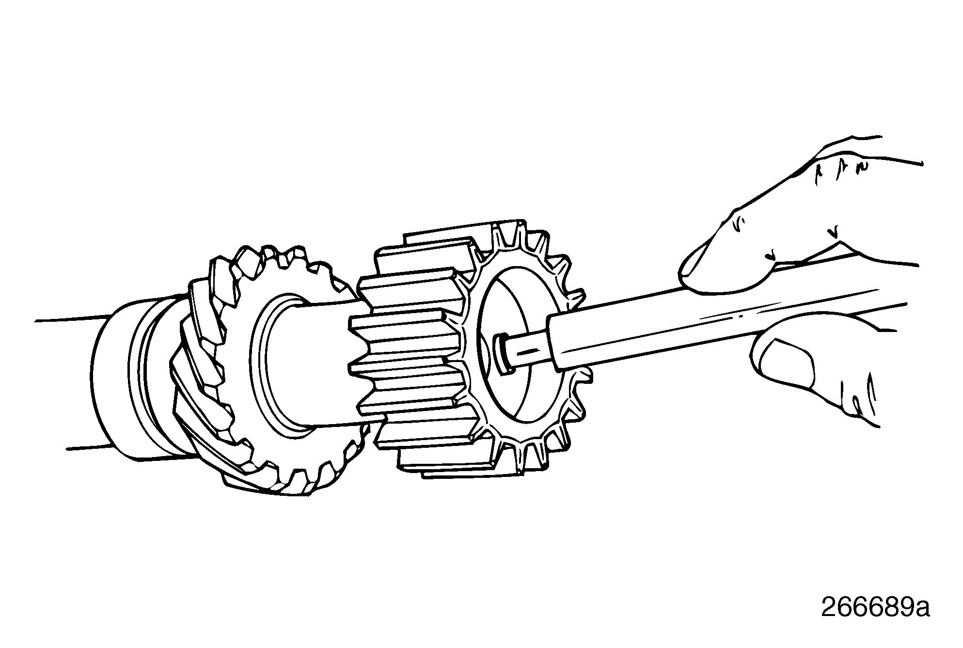
2.Position oil metering plug on a suitable driving tool.
178
3.Position the plug and installation tool squarely with the shaft bore.
179