1 minute read
REPAIR INSTRUCTIONS


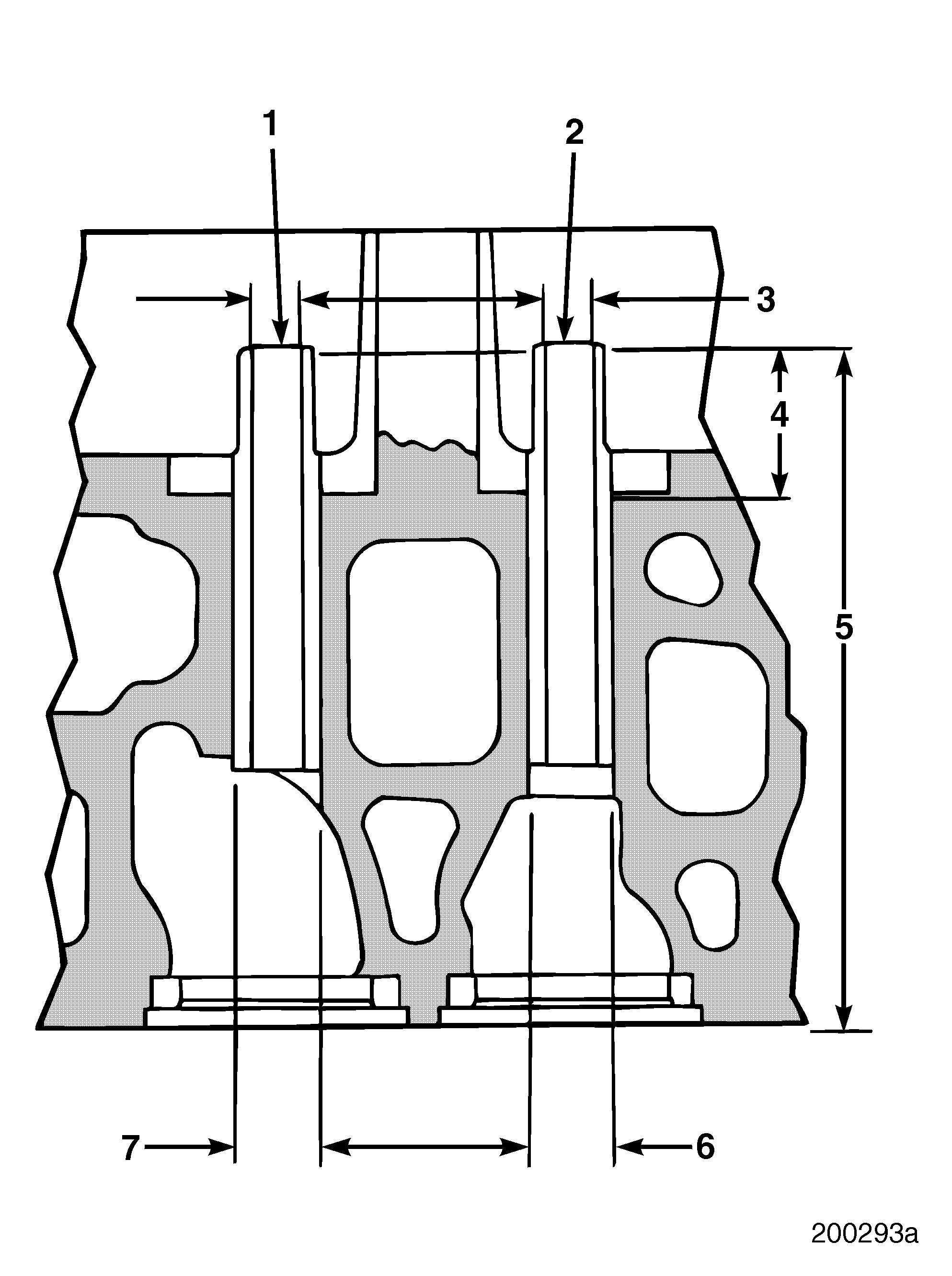
Valve Guides
Inlet and Exhaust Valve Guide Dimensions r Valve guide ID (3) 0.3745–0.3755 inch (9.512–9.538 mm) r Top end of guide to valve spring seat (4) 0.959 ± 0.040 inch (24.36 ± 1.016 mm) r Valve guide extension, fire deck to top of guide (5) 5.24 ± 0.03 inch (133.096 ± 0.762 mm) r Valve guide bore in head (6) 0.686–0.687 inch (17.424–17.450 mm) r Valve guide OD (7) 0.6881–0.6886 inch (17.478–17.490 mm)
Refer to Figure 212.
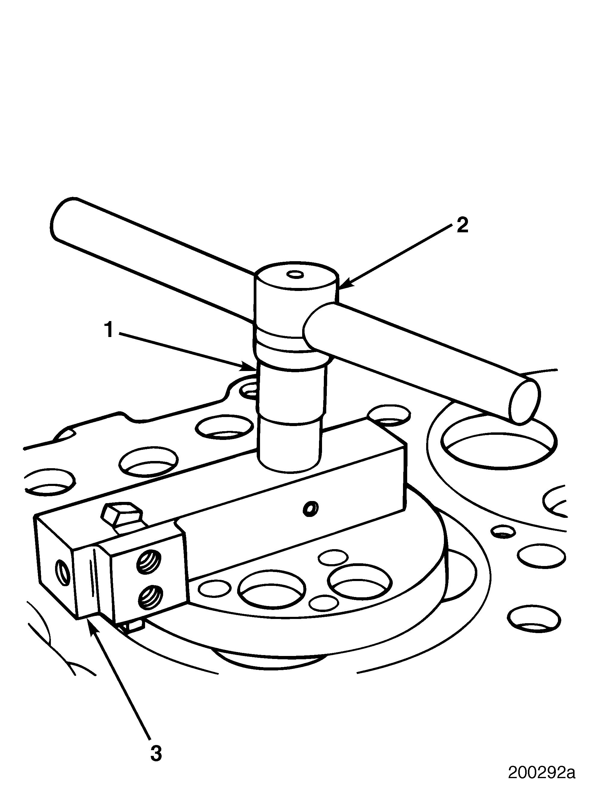
7.After groove is cut, remove cutter head and cutter base from cylinder head.
8.Use a honing stone to remove any burrs around fire ring groove.
9.Check fire ring groove depth with depth gauge J 26948 to verify that groove depth meets specification. If groove depth does not meet specification, recut as necessary.
10.Repeat above procedure with each fire ring groove cut.
To ensure proper groove depth, always adjust cutting tool height when cutting next groove.
Inspection


