1 minute read
REPAIR INSTRUCTIONS


Valve Seat Insert Counterbore r Valve seat at counterbore depth (3):
Refer to Figure 223.
Exhaust: 0.372–0.376 inch
(9.499–9.55 mm)
Inlet: 0.360–0.364 inch
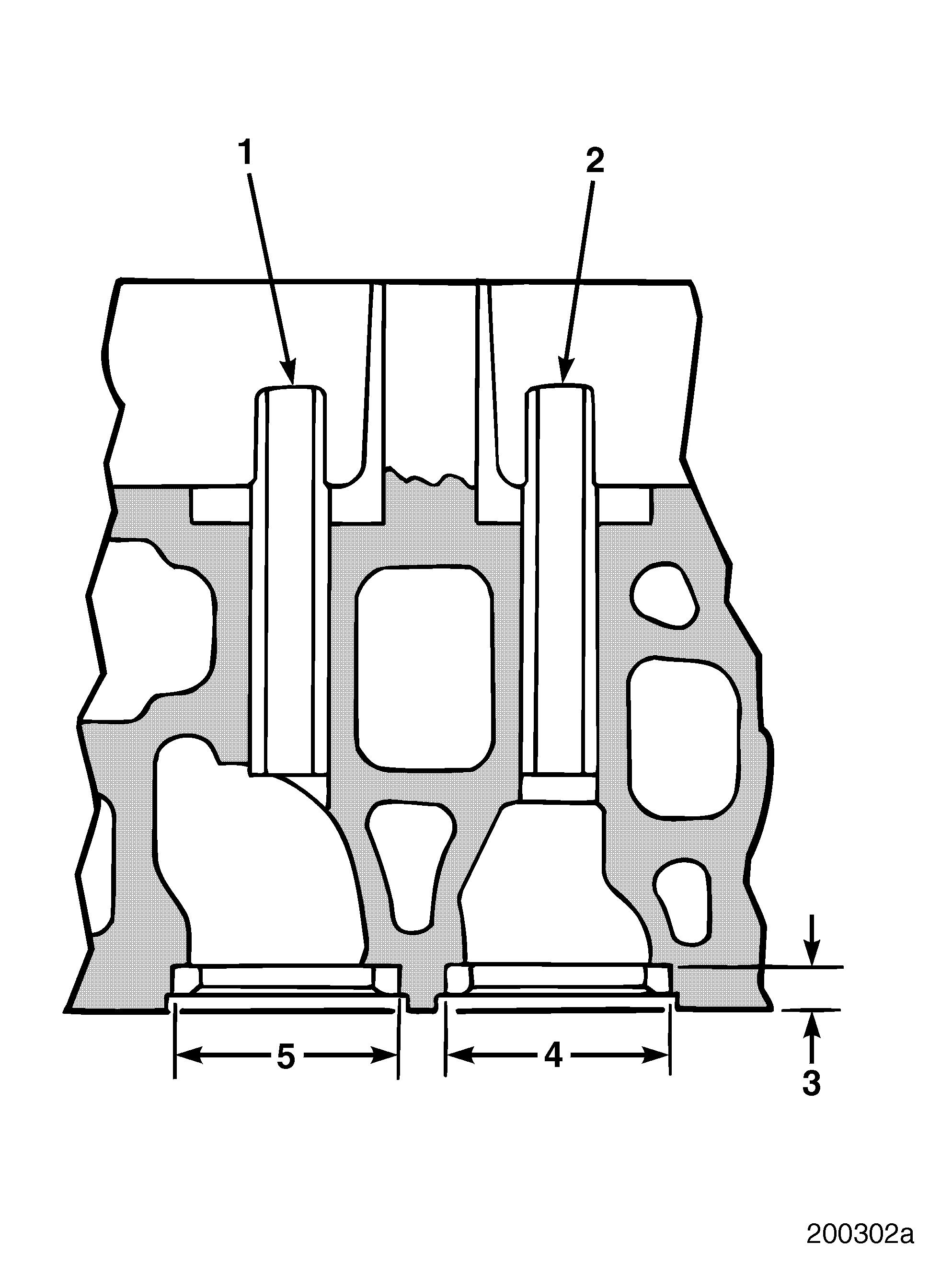
(9.144–9.246 mm) r Inlet valve seat insert counterbore diameter (4): 1.8285–1.8295 inches (46.4439–46.4693 mm) r Exhaust valve seat counterbore diameter (5): 1.6875–1.6885 inches (42.8625–42.8879 mm)
223
Inspection
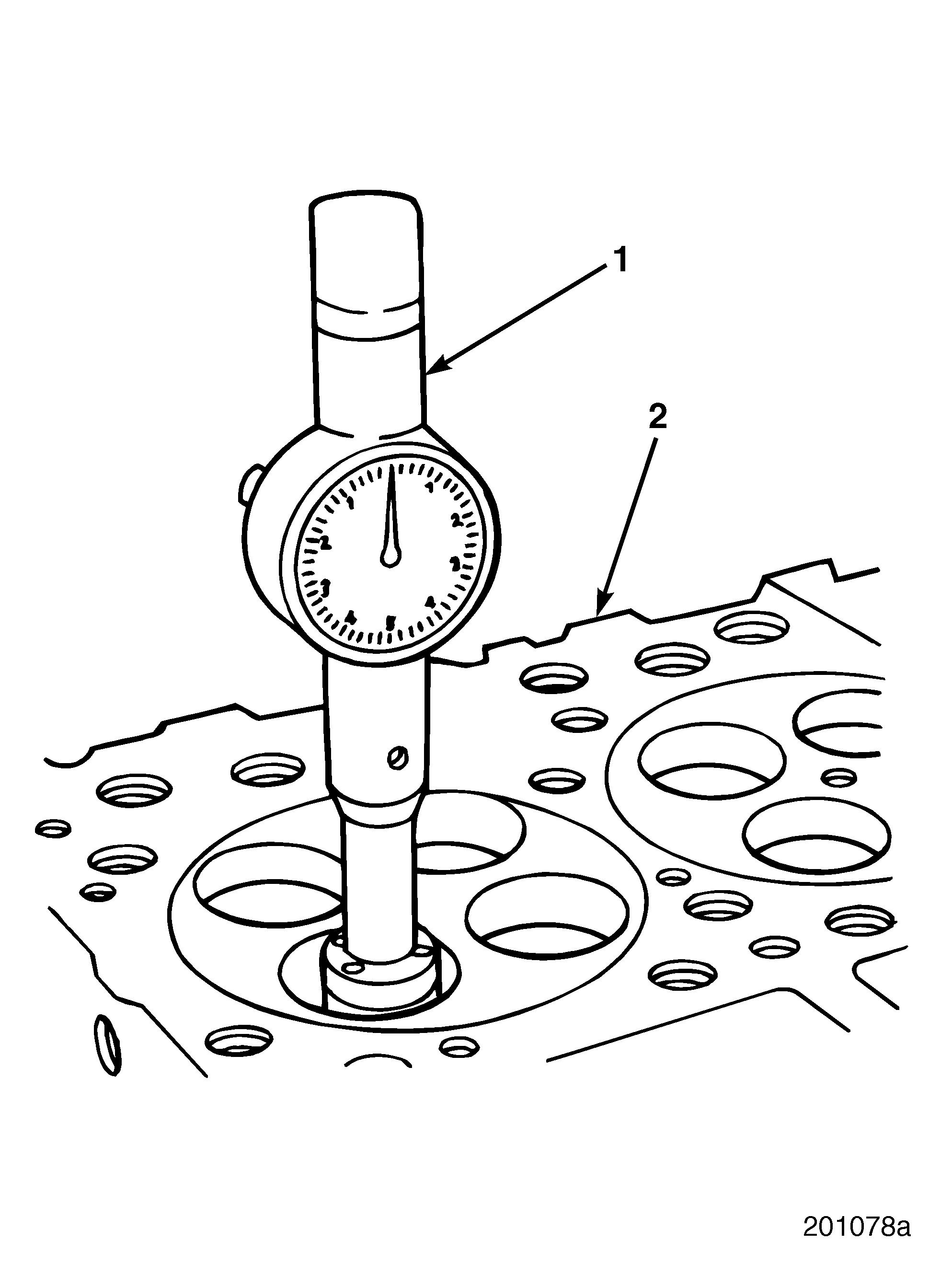
Refer to Figure 224.
1.With valve seat insert removed from cylinder head (2), clean surfaces thoroughly with wire brush.
2.Check surface finish for smoothness. Check counterbore diameter with an inside diameter micrometer (1). Refer back to specifications listed in Figure 223.
224
Page 169
Repair Instructions
Valve Seat Insert Installation r Inlet valve inserts: 20° 30′ ± 15′ angle r Exhaust valve inserts: 30° 15′ ± 15′
Oversize inlet and exhaust valve seat inserts are available in 0.005, 0.015, 0.031, 0.047 and 0.062 inch sizes if counterbore requires machining.
1.If required, machine the inlet and exhaust valve seat insert counterbores using tool HT77136.
Refer to Figure 225.
2.Position valve seat insert (1) over corresponding counterbore. Install inserts using valve seat insert installation set J 38586 (2). Use driver handle J 8092 (3) to drive valve seat insert into counterbore.
3.Grind inlet/exhaust valve seat inserts to specification.
Always use 30-degree valves with 30-degree valve inserts and 20-degree valves with 20-degree valve inserts. Excessive wear and possible failure results if 30-degree parts are matched with 20-degree parts.
If valve seat insert widths exceed specifications when grinding inserts, use a 15-degree angle grinding stone to obtain correct width.
Refer to Figure 226.
4.After grinding is completed, thoroughly clean valve seat insert.
5.Determine concentricity of each valve seat insert relative to valve guide. Valve seat runout is to be held within 0.001 inch (0.025 mm) Full Indicator Movement (FIM), with finished valve guide ID measurements made from snug-fitting arbor (1) and through-mounted into finished valve guides (2).

6.After valve insert has been ground and cleaned, determine position of contact area between valve and valve seat insert. Apply a dab of Prussian Blue to valve face at four points, 90 degrees apart.
7.Lower stem of valve into valve guide and allow valve face to rest on seat insert. Rotate valve 90 degrees on insert. Carefully remove valve without making contact with valve face. Properly ground inserts should have full pattern on insert.
Thoroughly clean cylinder head after checking valve seat inserts and before installing valves.


