1 minute read
REPAIR INSTRUCTIONS


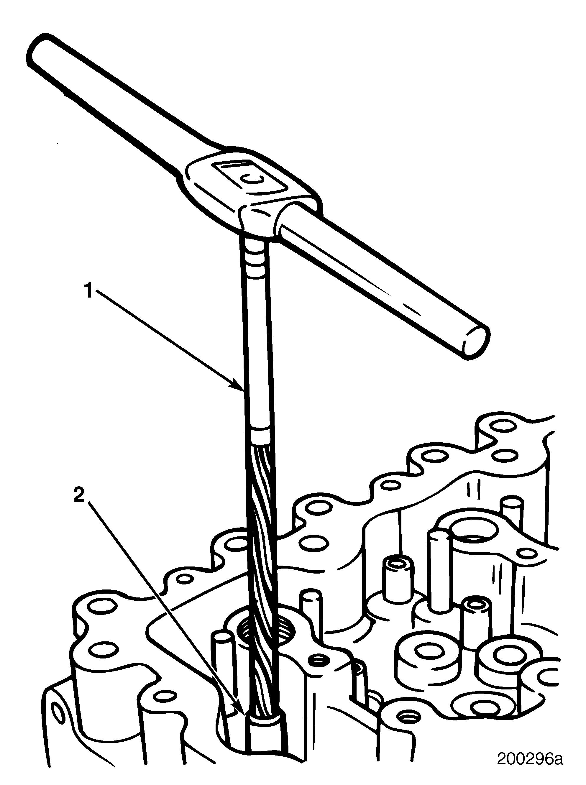
Valve Guide Removal
Clean exhaust valve guide OD (shoulder) before removal. Use a rotary brush to prevent scoring of exhaust valve guide bore.
Refer to Figure 215.
1.Insert valve guide remover J 37482 (1) into valve guide from deck side of the cylinder head (2). 215
Valve Guide Installation
1.Insert new valve guide into valve guide installer J 37809.
2.Oil OD of new guide before installation.
3.Press the valve guide into top of cylinder head using tool J 37809. Refer to Figure 216.
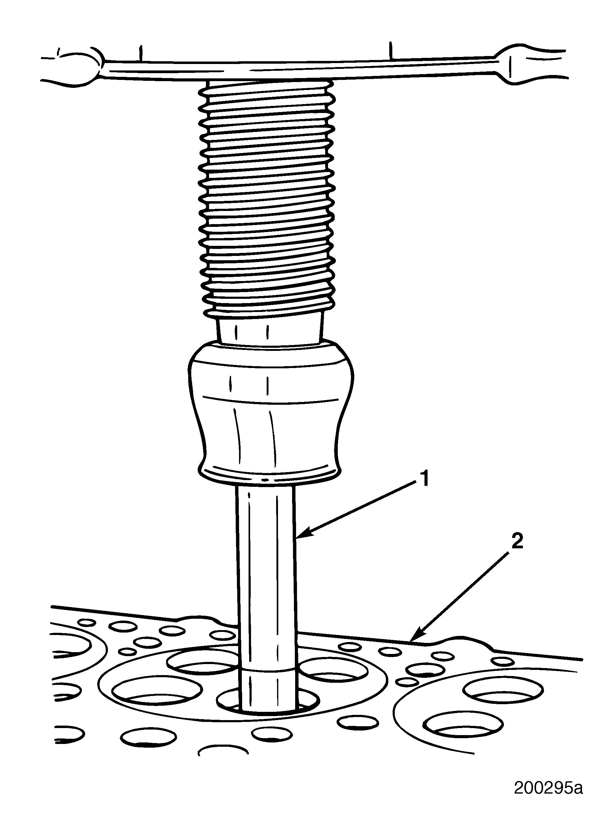
4.Using depth gauge, check extension of valve guide from valve spring seat to top end of the guide. 216
2.Press out old valve guides from cylinder head.
3.Check valve guide bore in the cylinder head for wear, cracks or other damage. Clean surfaces thoroughly and check ID measurement.
Page 165
Repair Instructions
Refer to Figure 217.
5.Using valve guide reamer J 37481 (1), ream new valve guide (2) to dimension. 217
INLET AND EXHAUST VALVE SEAT INSERTS
Valve Seat Insert Dimensions r Valve seat (3) insert face angle (1)
Refer to Figure 218.
Inlet: 20° 30′ ± 15′
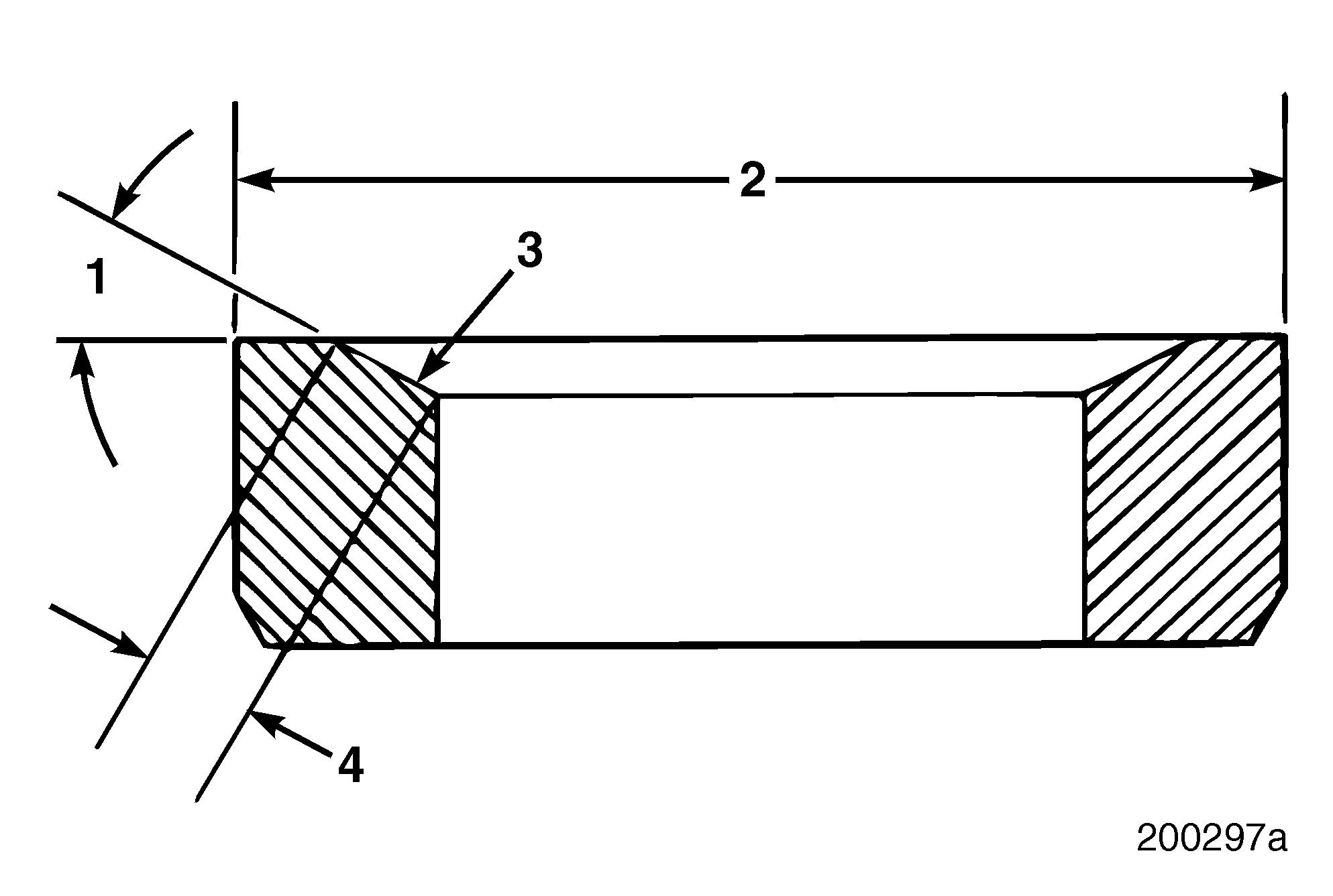
Exhaust: 30 ° 15′ ± 15′ r Valve seat insert diameter (2)
Inlet: 1.831–1.832 inches (46.507–46.533 mm)
Exhaust: 1.692–1.693 inches (42.977–43.002 mm) r Valve seat width (4) 0.066 ± 0.015 inch (1.676 ± 0.381 mm) 218
6.Thoroughly clean all metal debris from valve guide and surrounding area.
7.Install valves in cylinder head and check for binding, looseness and other conditions that may result in premature valve or valve guide failure.
Visually inspect valve seat inserts for looseness, cracks or other conditions that may result in improper operation. Replace as necessary.