
1 minute read
REPAIR INSTRUCTIONS


Exhaust Manifold Removal
1.To support the exhaust manifold during removal, insert two long guide studs (of the same thread as the manifold bolts, M12 x 1.75) into previously removed exhaust manifold bolt holes (fourth back from the front on the bottom and second back from the front on the top), as shown in Figure 115.

115
1. Bolt Length of 6.89 inches (175 mm)
2. Bolt Length of 6.50 inches (165 mm)
The exhaust manifold is a very heavy casting. To prevent personal injury, acquire assistance to help remove the manifold.
4.Remove the supporting guide studs and exhaust manifold gaskets from the cylinder heads. 117
3. Bolt Length of 6.10 inches (155 mm)
4. Manifold Guide Stud Locations

2.Remove the remaining exhaust manifold bolts. Note bolt lengths for reassembly (refer to Figure 115).
3.Remove exhaust manifold.
116
5.Discard gaskets.
Repair Instructions

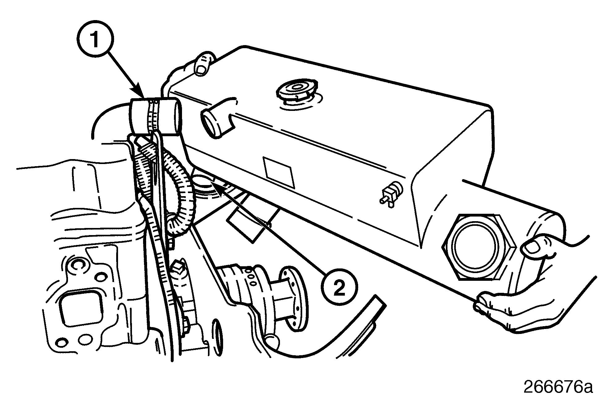
Heat Exchanger Removal
1.Loosen the two heat exchanger-to-bracket spring clamps.
2.Loosen the heat exchanger-to-oil cooler inlet tube hose spring clamps.

118
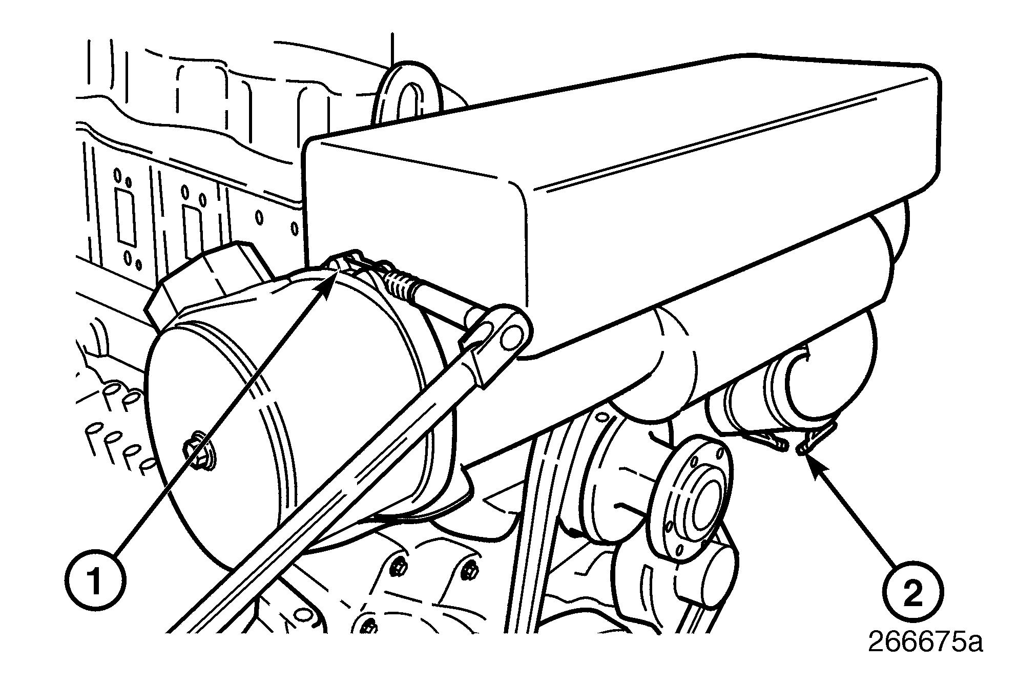
4.Remove the three heat exchanger bracketto-water pump capscrews.
Not shown, there is a screw on the backside of this bracket which attaches to a boss on the water pump housing which also must be removed.
Before removing these screws, the drive belts must be removed from the water pump pulley to prevent the belt tension from pulling the water pump loose. 120
3.Loosen
119
5.Remove the heat exchanger-to-water
121


