1 minute read
REPAIR INSTRUCTIONS


3.Lubricate the threads of the rocker arm bracket mounting capscrews with clean engine oil. Install the capscrews and torque to specification using torque wrench J 24407, or equivalent.
4.Adjust valve lash settings as applicable. Refer to “ENGINE SETUP AND ADJUSTMENTS” on page 270 for correct specification. 306
Rocker Arm Installation
DESCRIPTION
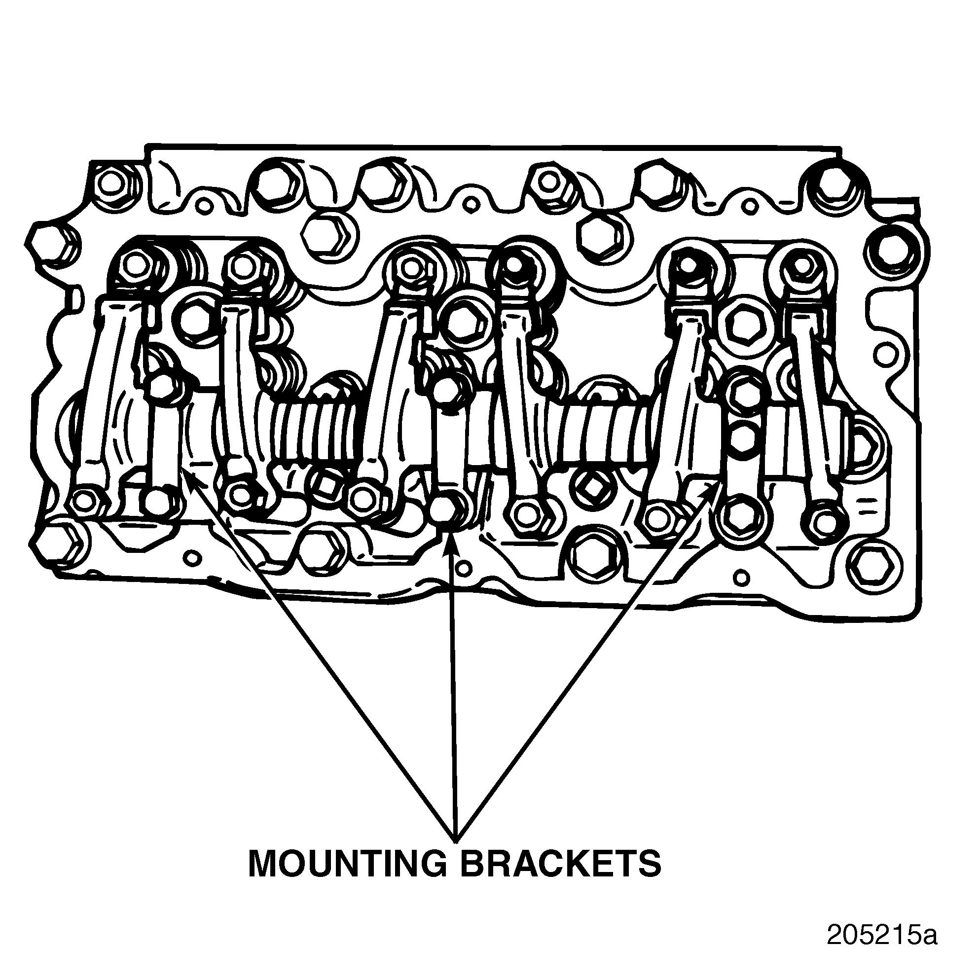
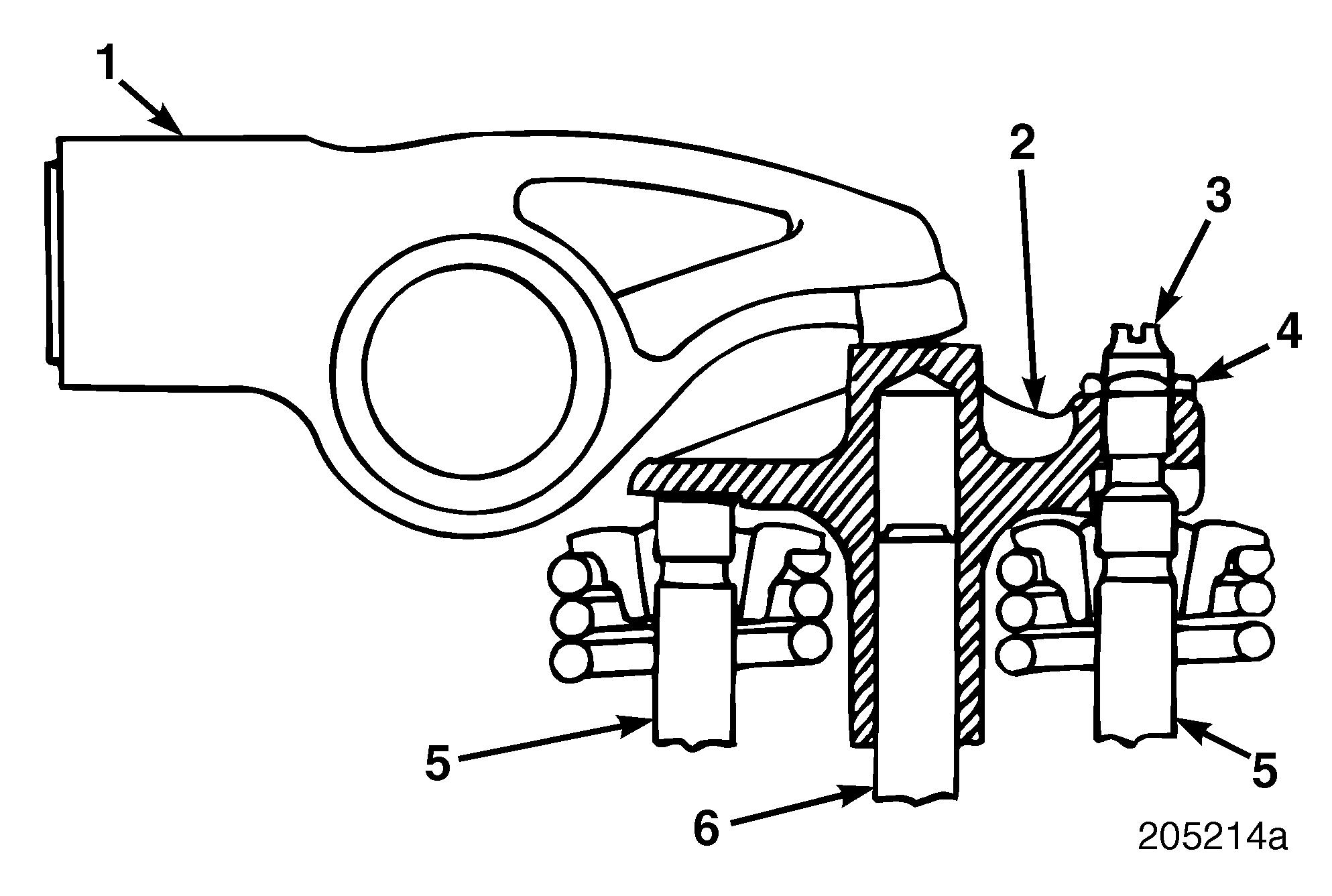
The valve rockers pivot on a shaft supported by three brackets per cylinder head. Two capscrews secure each bracket to the cylinder head. The rocker arms are operated by a camshaft through valve lifters and push rods extending through the cylinder heads. A coil spring returns each valve to the closed position, holding the rocker arm in contact with the push rod.
Installation
Refer to Figure 306.
1.Position the rocker arm assemblies on the cylinder heads.
2.Ensure that the ball end of the rocker arm adjusters are in position in the push rod cups.
Make sure that adjusting screws are retracted upward in the rocker arms. If extended far below rocker arm, the push rods can be bent when tightening the rocker arm assembly brackets.
Repair Instructions
Nozzle Holder Assembly Installation
DESCRIPTION
Each cylinder has a nozzle to ensure proper delivery of fuel that is metered and timed by the injection pump. The nozzle is positioned at the lower end of the nozzle holder.
The nozzle holder is positioned vertically in the cylinder head and centered in the cylinder between the four valves. The nozzle fuel inlet tube is inserted through the side of the cylinder head and the tapered end of the inlet tube seals the area between the tube and the nozzle holder. The tube is secured in position with a sleeve nut.
SPECIAL TOOL REQUIRED r Injection Nozzle Puller J 37093
Installation
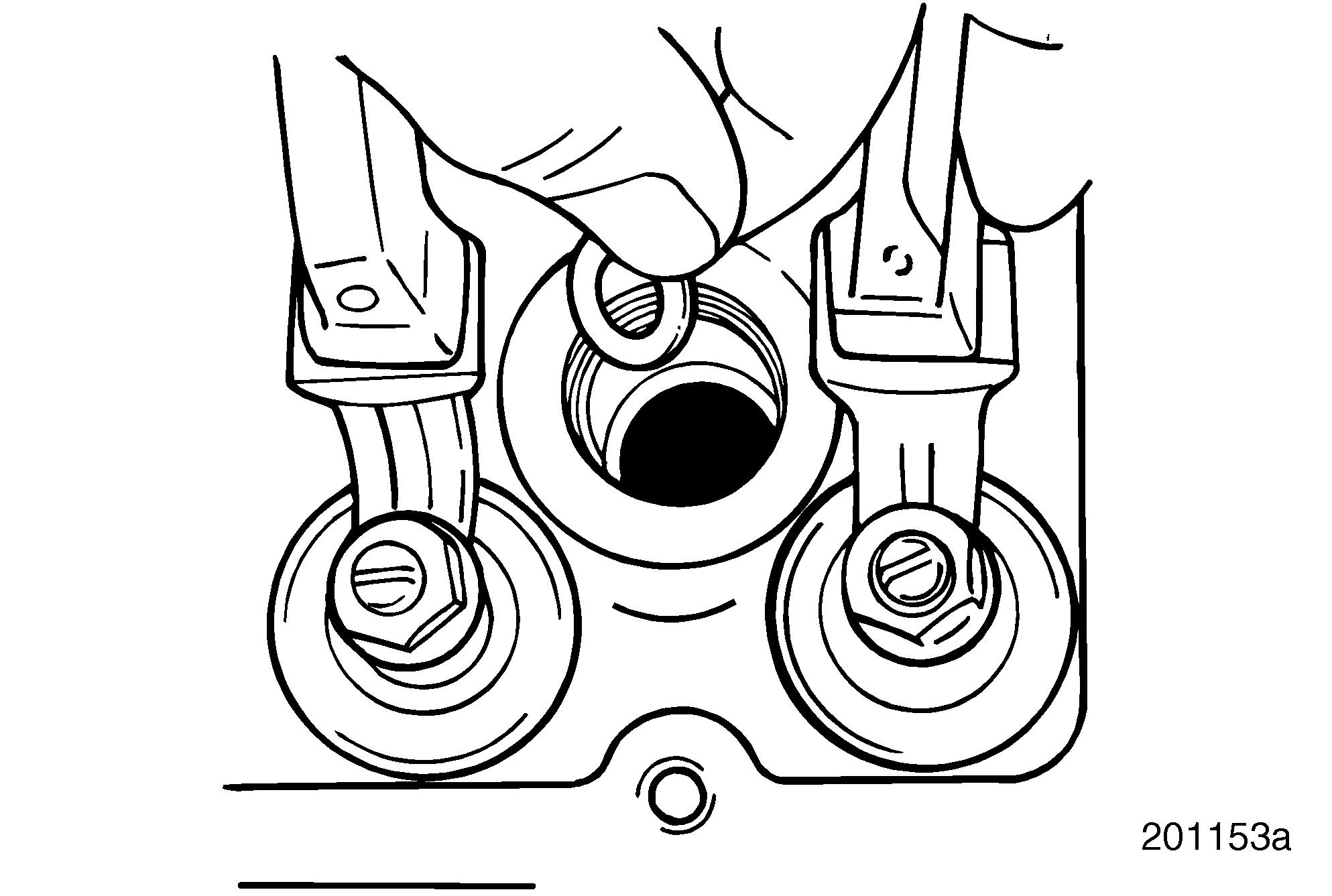
1.Insert a nozzle holder gasket in the bottom of the nozzle holder hole. Refer to Figure 307. Make sure the washer-type gasket is lying flat in the bottom of the nozzle holder bore.
An alternate method of installing the washer-type gasket is to hold it in place on the bottom of the nozzle with a small dab of grease instead of placing the washer in the hole. 307
2.Lubricate the nozzle holder surface and install O-ring on the nozzle holder.
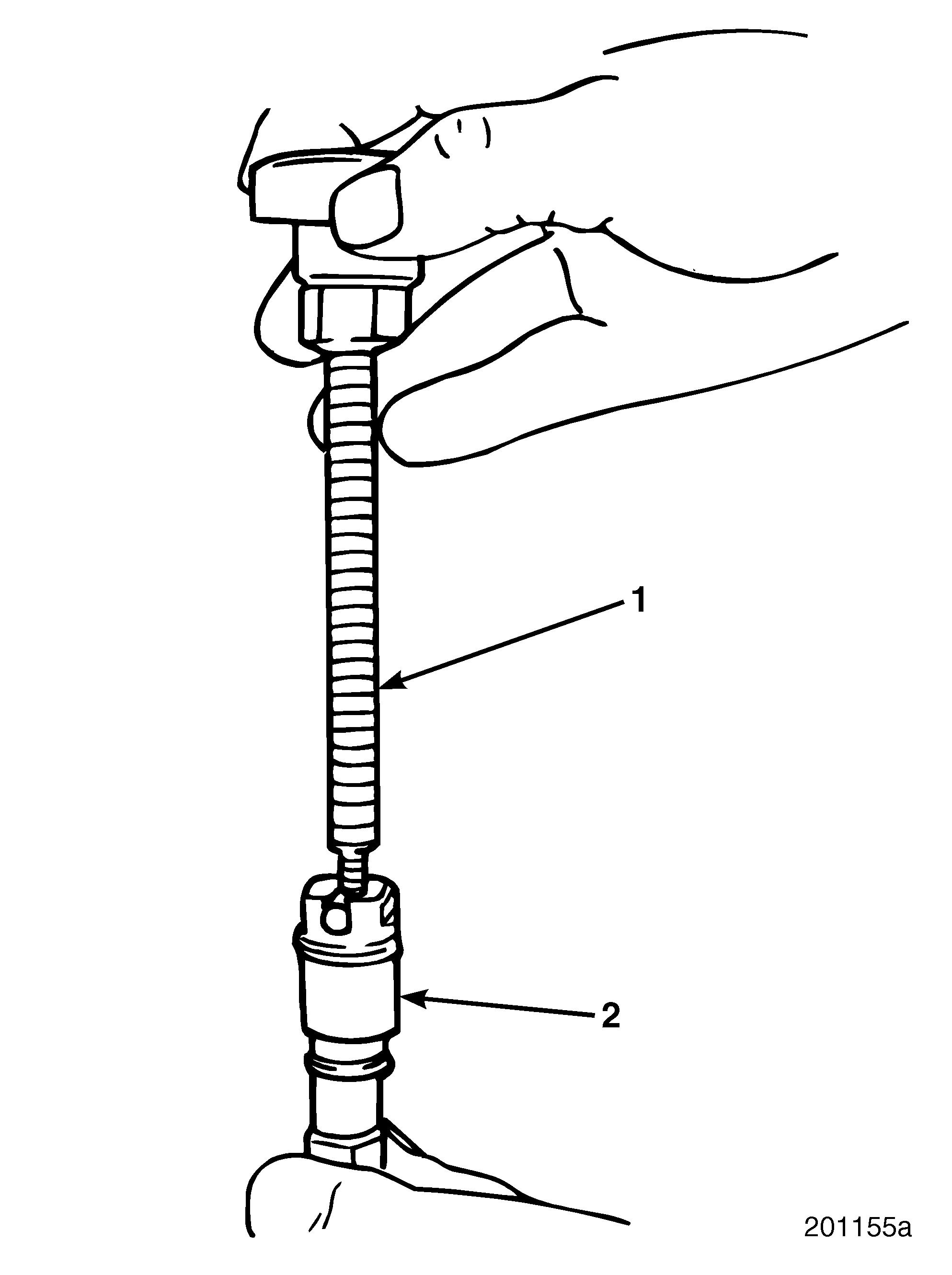
3.Thread injection nozzle puller J 37093 into the top of nozzle holder. Refer to Figure 308. 308
4.Insert nozzle holder in the nozzle holder hole. Be sure to align the locator ball in the nozzle holder with the socket in the cylinder head to ensure inlet tube alignment. Refer to Figure 309.
309


