2 minute read
REPAIR INSTRUCTIONS


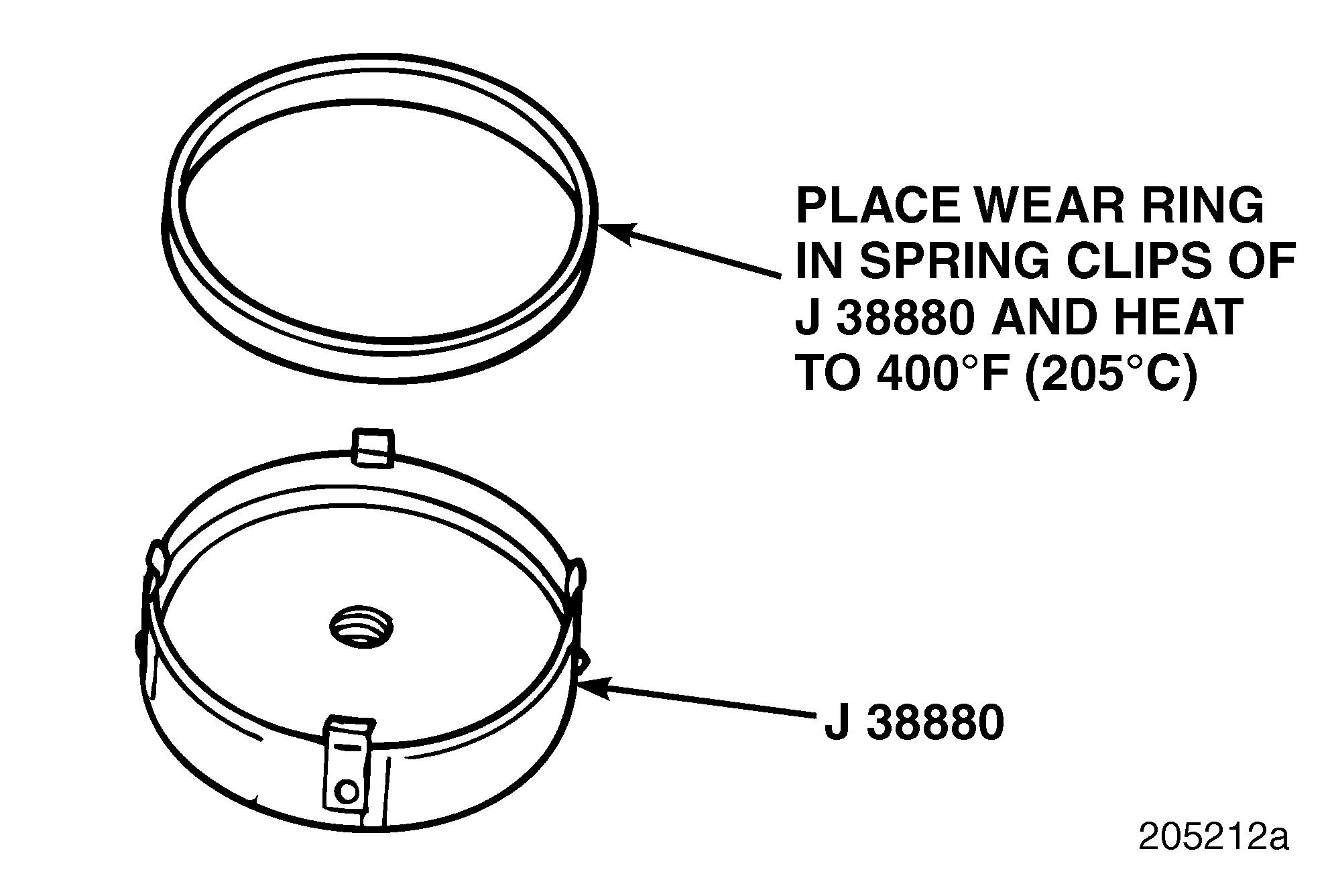
1.Position the wear ring in the spring clips of the wear ring installer J 38880 with the arrow pointing away from the installer tool. Refer to Figure 188.
188
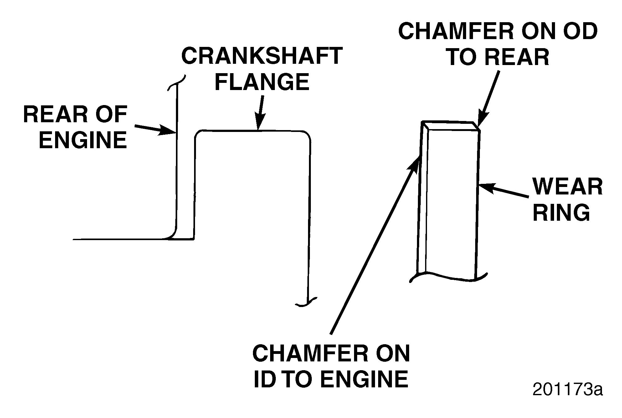
On some wear rings it may be difficult to determine the direction of the arrow on the inside diameter. In this case, ensure proper installation by installing the wear ring with the chamfer on the inside diameter toward the engine. The chamfer on the outside diameter of the wear ring must face away from the engine.
The crankshaft wear ring is a shrink fit on the crankshaft flange. Use wear ring installer J 38880 and universal driver handle J 8092 to install the ring to the proper depth.
187
2.Heat the wear ring and wear ring installer together in a temperature-controlled oven or on a hotplate, with the wear ring on the bottom and installed in the spring clips of the installer. Work as close as possible to the engine to avoid heat loss after heating the ring. Heat to 400°F (205°C). Do not install the driver handle at this time. This allows the wear ring to maintain sufficient heat until it is fully installed on the flange.
Do not heat the wear ring with a torch. This type of heat source will not heat the ring evenly.
3.Thoroughly clean and dry the crankshaft oil seal mounting flange.
4.After the wear ring is sufficiently heated, use heat-resistant gloves to install the universal driver handle J 8092 into the threaded hole in the center of the installation tool.
5.Remove the wear ring and installation tool from the oven or hot plate and immediately place in position on the crankshaft flange. Push the wear ring onto the flange until the installation tool is fully seated against the end of the flange. As the wear ring cools, it will shrink-fit onto the crankshaft flange.
6.Allow the wear ring to cool completely. Then remove the installation tool.
Page 147
Repair Instructions
Crankshaft Dowel Pin Replacement
The flywheel locating dowel hole, located directly opposite the manufacturing locator hole, is approximately 9/16 inch (14.29 mm) in diameter by 7/8 inch (22.23 mm) deep.
DOWEL PIN REMOVAL
To remove rear crankshaft dowel pin:
1.Using vise grips, securely grip dowel pin.
2.Rotate dowel pin back and forth while exerting outward pressure until pin is removed.
DOWEL PIN INSTALLATION
Refer to Figure 189.
To install a replacement crankshaft dowel pin:
1.Position dowel pin in a 0.5562-inch (14.1275 mm) diameter unthreaded hole in rear of crankshaft. The pin must be installed with the flat surface aligned parallel to the center of crankshaft, as shown in Figure 189.
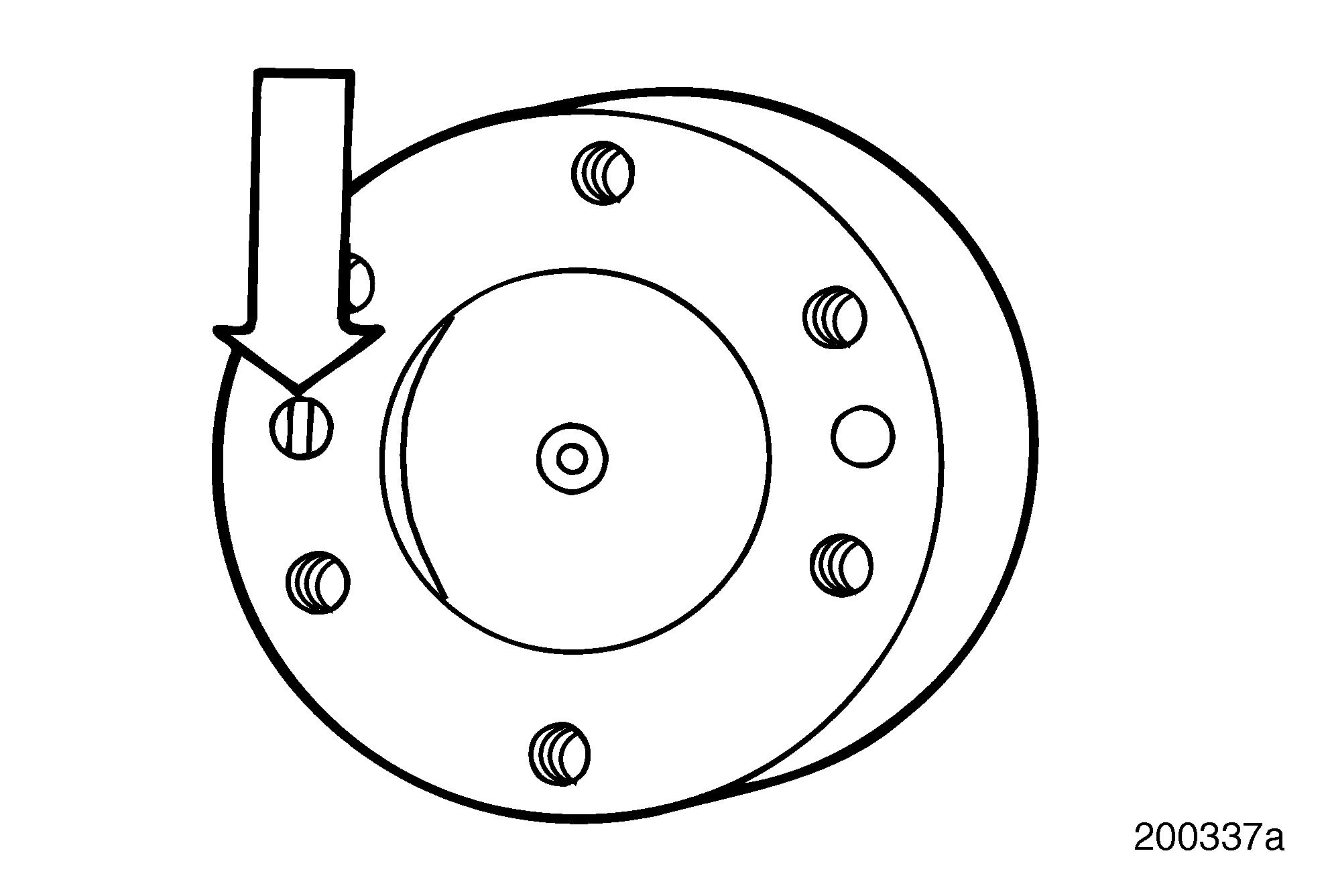
2.Use a suitable tool to drive the pin into the hole. The pin must be firmly seated and protrude 0.77 inch (19.56 mm) from the crankshaft.
189
Crankshaft Gear INSPECTION
After inspecting the crankshaft and determining that it is serviceable, inspect crankshaft gear for cracks and broken, worn or chipped teeth. If crankshaft gear is defective, it must be replaced.
Replacement
Refer to Figure 190.
1.Using a suitable puller such as J 21834-4A, remove gear and key.
The threads in the end of the crankshaft gear are M8 x 1.25.
2.Clean gear mounting surface. It should be free of grooves, scratches and burrs. Use a file, sandpaper or crocus cloth, as required.
Take care not to damage key slot while installing key.
3.Insert key (4) into key slot (3). Lightly tap key into slot with a soft metal hammer.
4.Heat replacement gear (1) to approximately 250°F (121°C) in a temperature-controlled oven or on a hot plate.
Wear protective gloves when handling heated crankshaft gear to prevent burns or personal injury.
Take care not to damage gear teeth while seating gear.


