1 minute read
REPAIR INSTRUCTIONS


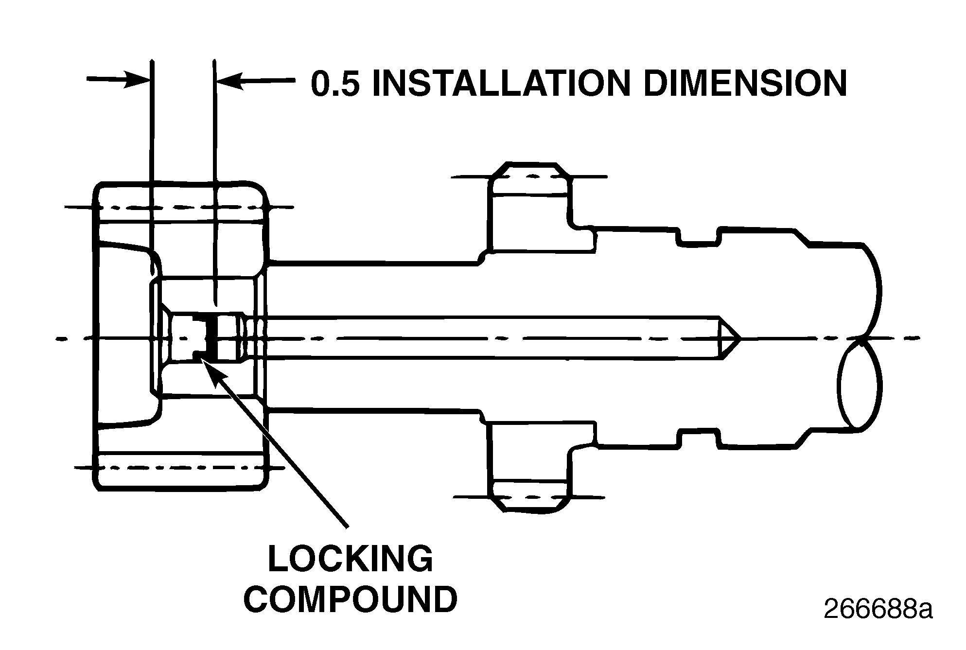
4.Drive the oil metering plug into the rear end of the auxiliary shaft to a depth of approximately 0.33 inch (8.38 mm) as measured from the lip side of the plug. The final installation depth of the oil metering plug should be no more than 0.5 inch (12.7 mm) as measured from the inner face of the plug as shown in Figure 180.
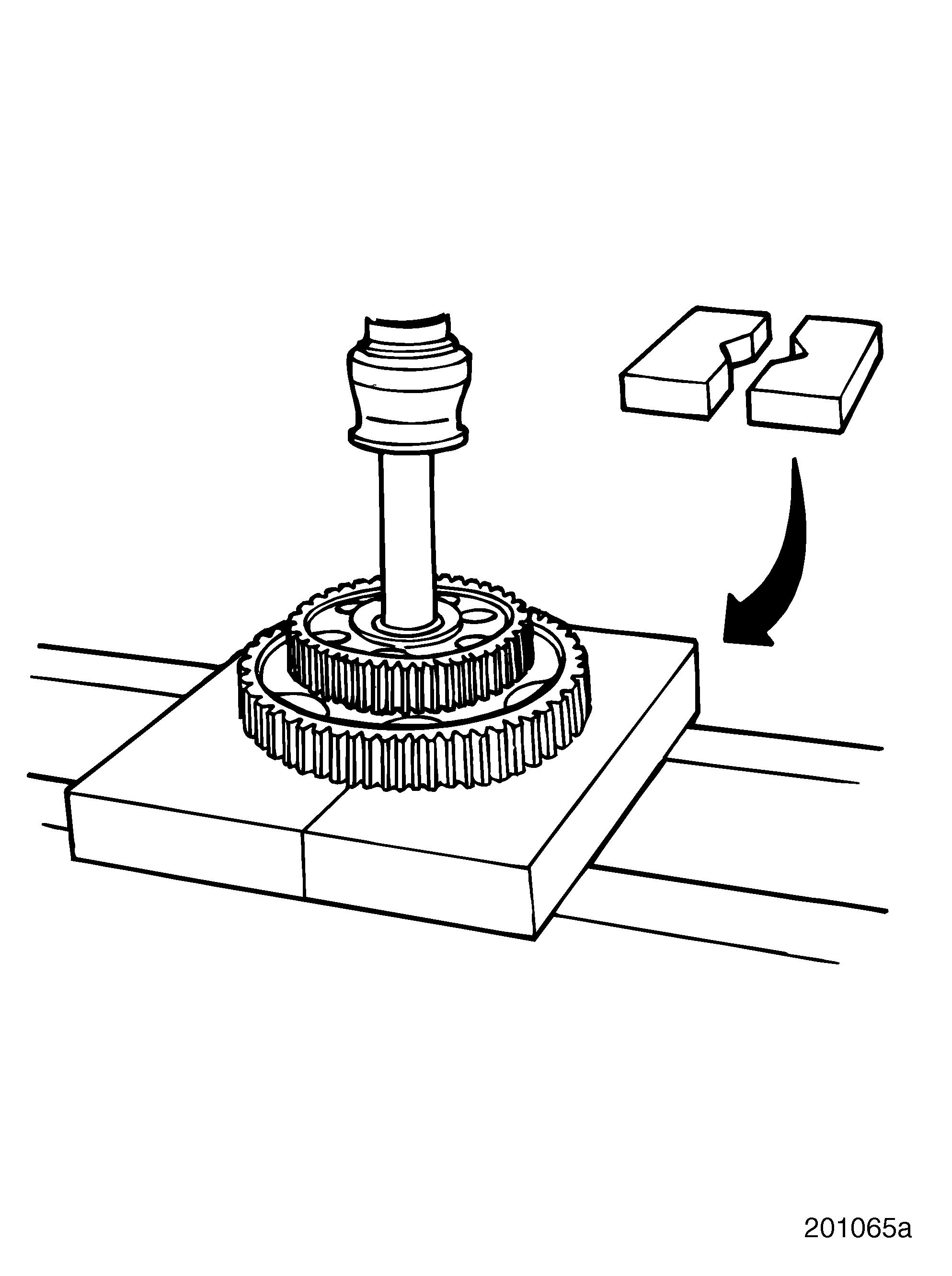
1.Position two adequate steel plates on the press to support camshaft gears. The plates should have a 2-1/2 inch (63.5 mm) hole cut out in the center when placed side by side, or similar size V-grooves, to allow clearance for the shaft journals and greater support for the gears.
2.Set camshaft, supported by the gears, into the press.
3.Using a suitable arbor, press camshaft out of camshaft gear and fuel injection pump drive gear.
Make sure there is enough clearance between the end of the camshaft and the floor while removing the gears. Do not let camshaft fall or strike the floor when pressed from the gears. The camshaft can be bent easily, and the bend may go unnoticed. Installing a bent camshaft in the engine could result in cam bushing failure.
4.Remove the thrust washer.
Camshaft
DESCRIPTION
The gear-driven carbon steel M-E7 camshaft, with its large journal bearing diameter of 2.689 inches (68.301 mm), provides excellent bearing unit loading and allows the use of large, durable camshaft lobes. M-E7 engine camshaft gears are pressed onto the camshaft.
DISASSEMBLY
An extremely tight interference fit holds the cam gears onto the camshaft. Ten tons of force are required to remove the gears. When cam gear installation or removal is required, use the following procedures.
A considerable amount of force may be necessary to remove damaged or spun gears. DO NOT apply more than 25 tons (22.7 metric tons) of force to gears. Doing so may shatter the gears and result in severe personal injury.
Refer to Figure 181.
Page 141


