2 minute read
REPAIR


Lubrication System Components Inspection
Oil Cooler Assembly Inspection and Repair
DESCRIPTION
The oil cooler assembly is located near the left front of the engine. Engine coolant from the heat exchanger flows through the lower tube and hose assembly, into a chamber in the oil cooler. The coolant then flows into the water pump.
The oil pump sends engine oil through the inlet port of the oil cooler into the cooling chamber. Heat from the engine oil is transferred through the chamber walls to the engine coolant. Cooled oil exits the oil cooler through the oil outlet port, flows through the oil filters, and then into the engine.
This engine features a “removable-bundle” type oil cooler. Periodic visual inspection of the oil cooler will indicate condition of gaskets, O-ring and core. If a problem exists, these components can be serviced separately rather than replaced as an assembly.
The presence of engine oil in the engine coolant may indicate internal engine problems or worn, loosened or damaged parts within the oil cooler. Continued operation under these conditions may result in severe engine damage.
Repair Instructions
DISASSEMBLY
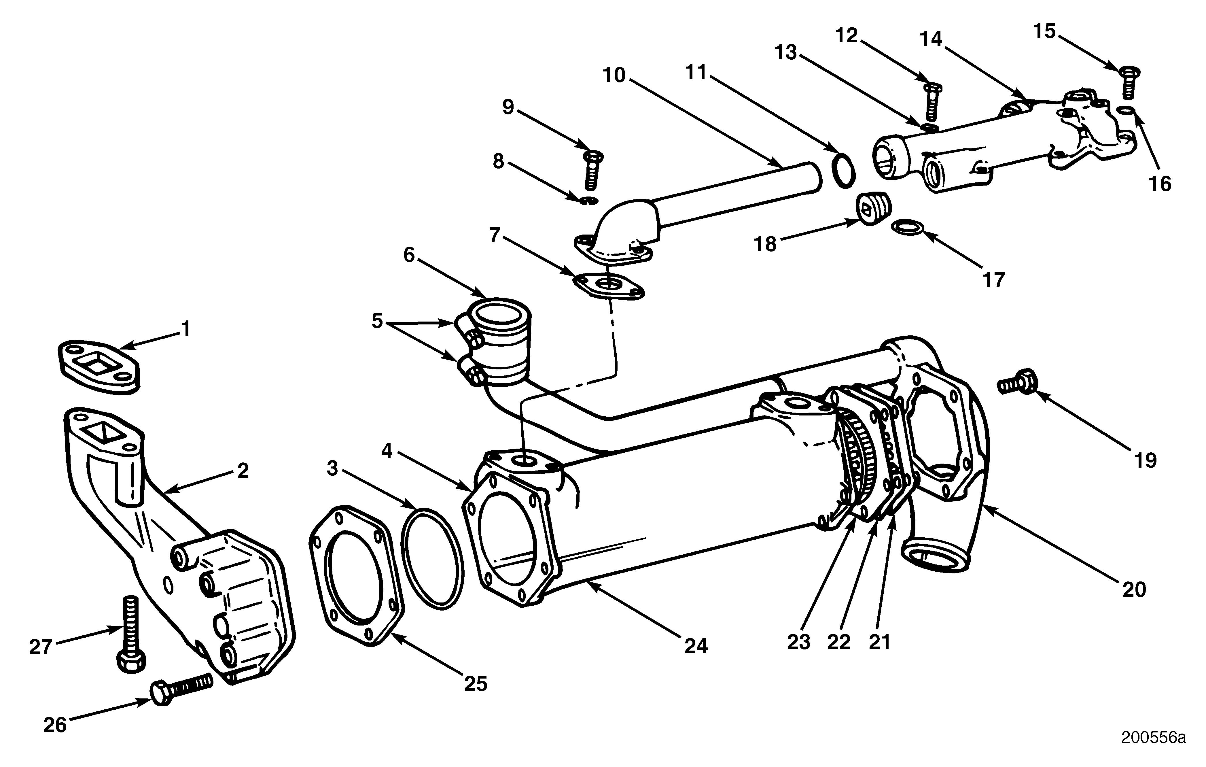
Refer to Figure 239.
1.Remove coolant inlet end cap (20) by removing six capscrews (19).
2.Remove coolant outlet end cap (2) by removing six capscrews (26).
3.Remove bundle (22) from coolant inlet end of housing (24).
4.Remove O-ring (3) from coolant outlet end of housing.
5.Clean gasket material from all surfaces.
Inspection
Refer to Figure 239.
1.Visually inspect housing (24) for cracks which may cause a leak. Replace housing if damaged.
2.Check oil cooler bundle (22) for leaks by pressurizing with air to 80 psi (552 kPa) and submerging it in water. If a leak is detected, replace with new bundle.
ASSEMBLY
Refer to Figure 239.
Lubricate and install O-ring (3) in groove at coolant outlet end of oil cooler housing (24).
1.Apply Permatex® gasket sealer on coolant inlet flange before installing gasket (23).
2.Install gasket (23) on coolant inlet end of housing (24).
3.Apply Permatex gasket sealer on top of gasket.
4.Install bundle (22). If necessary, tap bundle with soft-faced hammer to seat bundle past O-ring (3).
The alignment notch in the bundle end flange must be positioned at the top for proper installation.
5.Apply Permatex gasket sealer on bundle end.
6.Place gasket on bundle end.
7.Apply Permatex gasket sealer on top of gasket (21) before installing inlet cap (20).
8.Install coolant inlet end cap and secure with six capscrews (19).
9.Torque coolant inlet end-cap capscrews to 20 lb-ft (27 N•m) using torque wrench J 24405, or equivalent.
10.Apply Permatex sealant to both sides of gasket (25) and install on mounting flange (4) of housing.
11.Install coolant outlet end cap (2) with six capscrews (26).
12.Torque coolant outlet end-cap capscrews to 20 lb-ft (27 N•m) using torque wrench J 24406, or equivalent. Refer to Figure 240.
13.Pressure-check oil cooler for leaks by installing a test plate (4) with air fitting (3) as follows: a.Position a rubber gasket (5) and test plate (4) on mounting flange (1) and secure with mounting capscrews (2).


