6 minute read
MAINTENANCE


Raw Water Cooling System
Drain at the end of each boating season.
Sea Strainers
Inspect sea strainers daily. Clean sea strainers at least annually. Clean more often if surface seaweed growth or water contamination levels are fairly high.
COOLANT CONDITIONER CHANGE
23
Coolant Filter/Conditioners are used in the M-E7 marine engines to filter impurities such as scale or sand from the coolant. Filter elements are treated with chemicals that soften coolant water, minimize scale deposits, maintain an acid-free environment and act as a rust preventive. Coolant filter/conditioner elements should be replaced every 150 hours or annually, preferably at the beginning of the boating season.
Correct coolant conditioning must be maintained to provide maximum engine block and cylinder sleeve protection. On wet sleeve engines, a minimum nitrite level of 1200 ppm and a minimum pH of 8.5 is required. Changing the coolant conditioner at the specified 150-hour intervals ensures that the proper level of protection is maintained in the cooling system. Coolant conditioners contain a reduced solids chemical inhibitor package that allows coolant conditioner change intervals to coincide with the recommended oil change intervals.
If the cooling system is protected by a coolant filter/conditioner, the element should be replaced every 150 hours or annually, whichever comes first.
When changing the coolant conditioner, shut the engine OFF. Keep the engine stop control in the OFF position. To avoid injury when removing the heat exchanger cap, turn the cap counterclockwise to the first stop. DO NOT depress the heat exchanger cap until the pressure has dissipated. After all pressure has completely dissipated, press the cap downward and continue turning to remove.
To install a new coolant conditioner:
1.Relieve cooling system pressure by removing the heat exchanger cap.
2.Using tool J 29927, or equivalent, remove the coolant conditioner.
3.Clean the coolant conditioner mounting surface.
4.Apply a light film of engine oil to the sealing gasket of the replacement coolant conditioner.
5.Install the new coolant conditioner until the gasket contacts the base and then tighten an additional 1/2 to 3/4 turn.
6.Reinstall the heat exchanger cap. Start the engine and check for leaks.
7.Replenish the cooling system with the proper mixture of coolant as necessary.
Aftercooler Maintenance
Cleaning Aftercooler Internal Components
To clean the internal components of the aftercooler, the side covers, as well as both top and bottom covers, must be removed to allow access to the fins of the aftercooler. Cleaning of both the raw water and air sides of the aftercooler is recommended seasonally before the vessel is stored for the winter or if a cooling deficiency dictates cleaning is required.
REMOVING AFTERCOOLER FROM ENGINE
1.Close the engine sea water seacock.
2.Drain sea water from the raw water cooling system by separating the outlet hose at the raw water pump.
The entire raw water cooling system will drain back through the removed raw water outlet hose. This system contains many gallons of water. Be prepared to catch the water in buckets or allow the bilge pump to pump it out of the hull.
3.Loosen the hose clamp attaching the aftercooler water discharge tube to the aftercooler. When the aftercooler is removed, it will pull out of the tube.
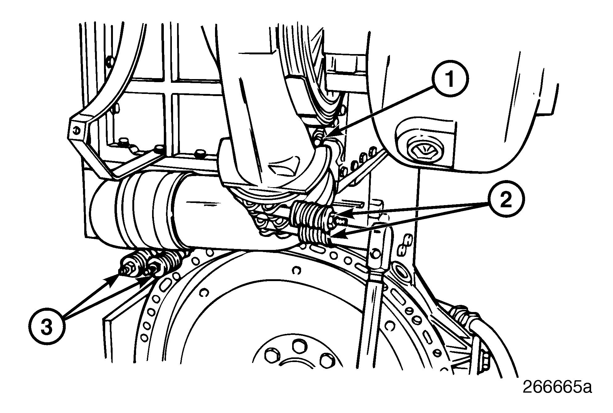
4.Remove the blow-by recirculation unit (AIRSEP®) from the rear of the engine by removing the support bracket fasteners and separating the oil drain back hose. Then loosen the spring-type hose clamp that connects the blow-by recirculation unit (AIRSEP®) to the turbocharger compressor.
5.Remove the aftercooler from the engine by first separating the air inlet tube hose clamps at the turbocharger compressor. Loosen the turbocharger compressor clamp and rotate the compressor up to allow the removal of the air inlet tube.
6.Remove the aftercooler air outlet tube by loosening the hose clamps at the outlet from the aftercooler and at the intake manifold. Remove tube by pulling up at the intake manifold, then away from the aftercooler.
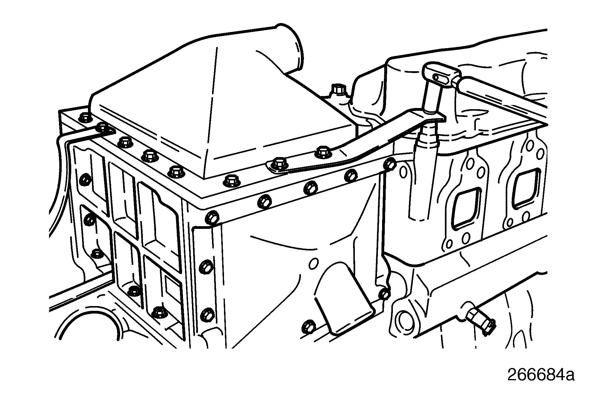
8.Remove the aftercooler bracket to flywheel housing bolts and remove the aftercooler.
7.Continue removing the aftercooler by loosening and removing the bolt that attaches the top cover bracket to the cylinder head bolt. 27
AFTERCOOLER CLEANING (AIR SIDE)
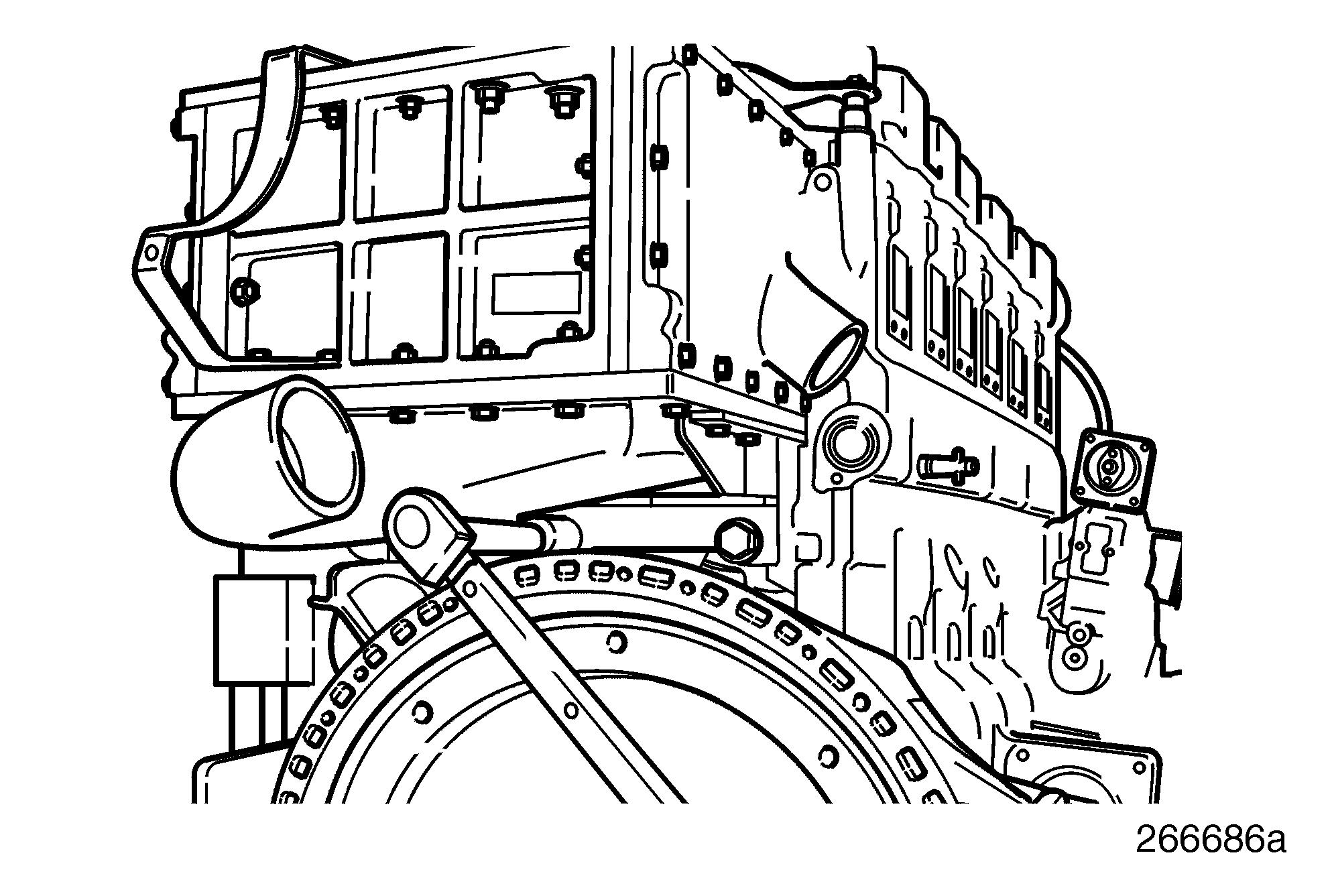
1.Remove the capscrews securing the aftercooler top outlet cover and the bottom inlet cover. Remove the upper and lower brackets. Aftercooler covers can now be separated from the aftercooler body by tapping with a brass or dead blow hammer to overcome the adhesive qualities of the gasket. 29
2.Scrape off any old gasket material from the aftercooler body.
3.Place the aftercooler body on newspapers and spray the now-exposed heat transfer fins using spray cans of carburetor cleaner (suitable for aluminum). Saturate the cooler until all oil and carbon is loose. Follow-up by steam cleaning the carburetor cleaner saturated fins until all loose contaminants have been removed. If necessary, continue spraying with carburetor cleaner and steam cleaning until cooler fins are clean.
Follow directions on carburetor cleaner can. Use only in a well-ventilated area. Dispose of carburetor cleaner waste properly.
A pressure washer may be used instead of a steam cleaner, but care must be used to avoid damage to the aftercooler fins.
4.The now-clean aftercooler fins must be blow dried with compressed air and then allowed to air dry in front of a fan for one hour.
5.Using new gaskets, install the bottom inlet cover and the top outlet cover. Insert and tighten the cover capscrews to specifications along with the top cover bracket and lower support bracket. Proceed to “INSTALLING AFTERCOOLER ONTO ENGINE” on page 60. 30
AFTERCOOLER CLEANING (SEA WATER SIDE)
1.Remove the capscrews securing the aftercooler top outlet cover and the bottom inlet cover. Remove the upper and lower brackets. Aftercooler covers can now be separated from the aftercooler body by tapping with a brass or dead blow hammer to overcome the adhesive qualities of the gasket.
2.Remove the capscrews securing the aftercooler inlet and outlet sea water side covers. Aftercooler side covers can now be separated from the aftercooler body by tapping with a brass or dead blow hammer to overcome the adhesive qualities of the gasket.
3.Remove any visible debris (grass, sea weed, impeller pieces, etc.) and scrape off any old gasket material from the edge of the aftercooler body.
4.Using a wire brush, remove salt from the end plates.
5.Clean (rod out) the inside of the tubes of the aftercooler using a gun (firearm) cleaning kit or bore brush. A .22 caliber rod with enough extensions to push completely through the tubes works well. Do not try to reverse direction of the rod as the brush is too large to be reversed in the tube. A pellet gun brush (.18/.19 caliber) should also work. Push the brush through each tube and blow out with compressed air.
6.Reassemble the side sea water covers using new gaskets and tighten all fasteners to specification. The new gaskets are oversize and will require trimming (after assembly) to match the top and bottom surfaces. A single-edge razor-type window paint scraper works best.
7.Apply Loctite® 271 to the three bolts on the top and the three bolts on the bottom of the sea water covers that protrude into the fin area. The Loctite® will seal air from leaking out of the bolt threads.
8.Using new gaskets, install the bottom inlet cover and the top outlet cover. Insert and tighten the cover capscrews to specifications along with the top cover bracket.
Installing Aftercooler Onto Engine
1.Position the aftercooler on the top of the flywheel housing, being careful to guide the water discharge fitting into the water discharge tube. Install the two aftercooler support bolts and tighten to specifications. Tighten the water discharge tube hose clamp per specification.
2.Continue installing the aftercooler by inserting the top cover bracket onto the cylinder head bolt capscrew. Tighten capscrew to specifications.
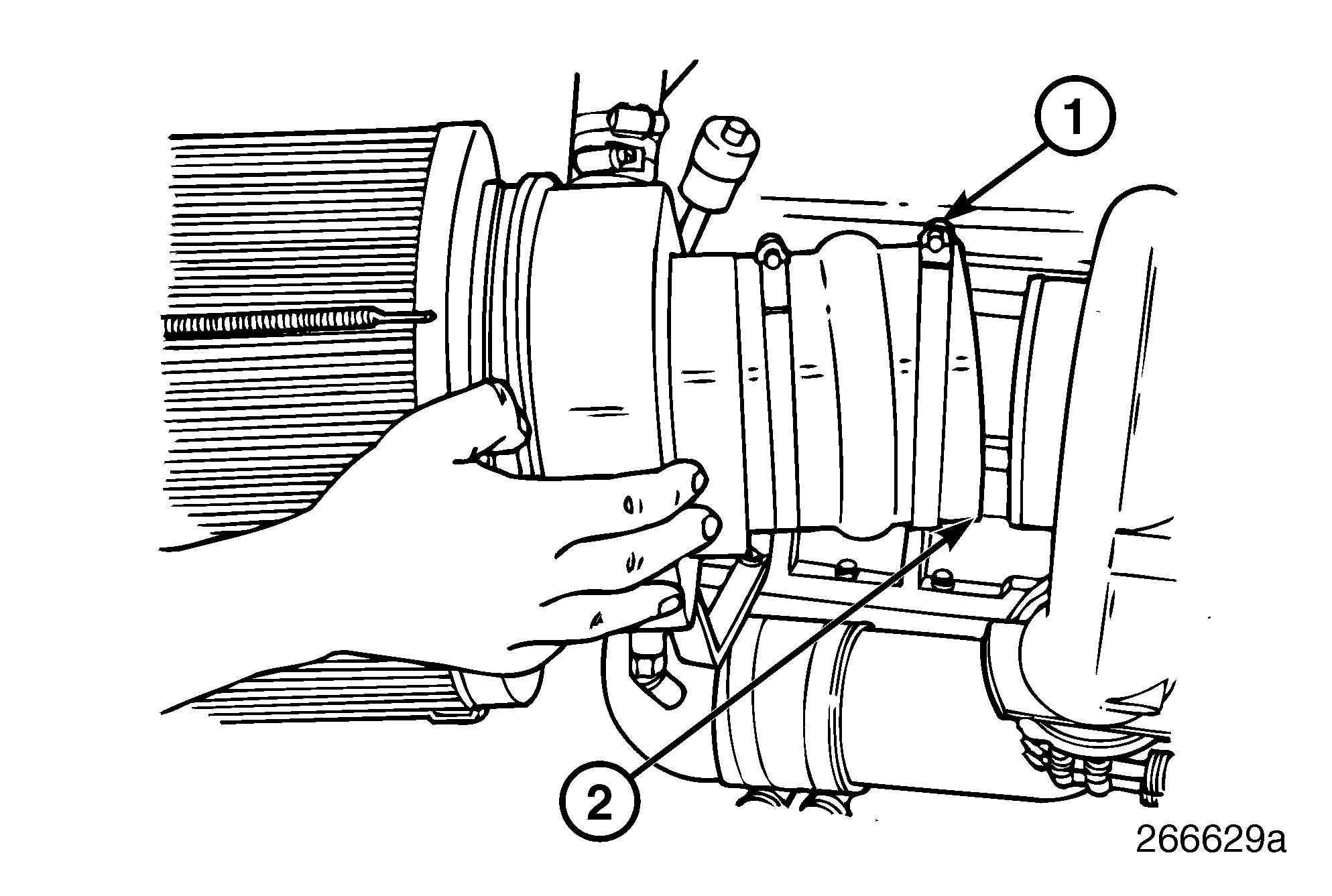
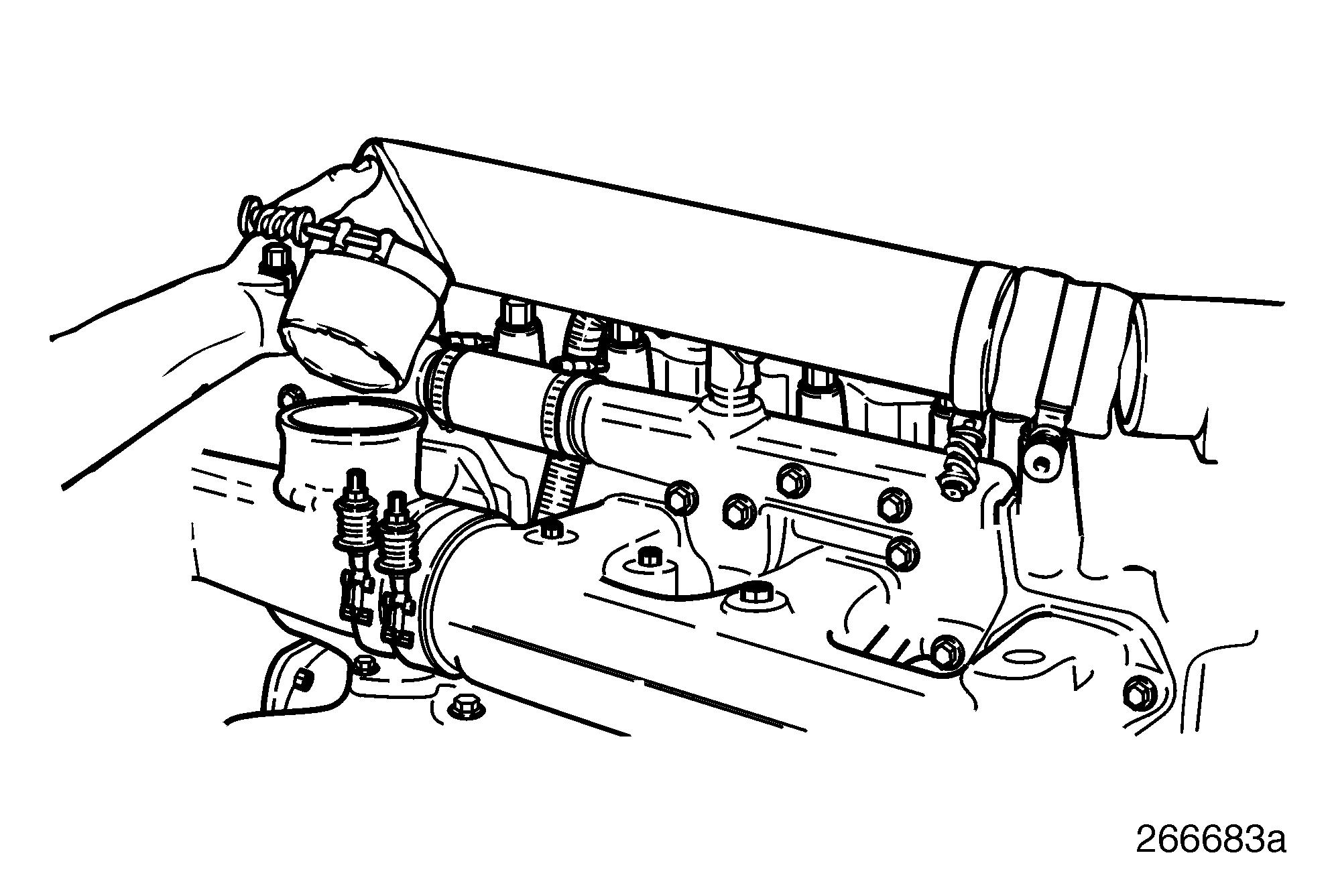
3.Position the air inlet tube, hoses and spring clamps between the aftercooler and the turbocharger compressor outlet. Correctly position the turbocharger compressor and tighten the compressor retaining clamp in this position. Position the four inlet tube hose spring clamps on the aftercooler and the turbocharger ends of the tube as shown in Figure 35. Tighten the hose clamps to specification.
1. Turbocharger Compressor Clamp
2. Turbocharger Compressor to Aftercooler Inlet Tube Hose Clamps
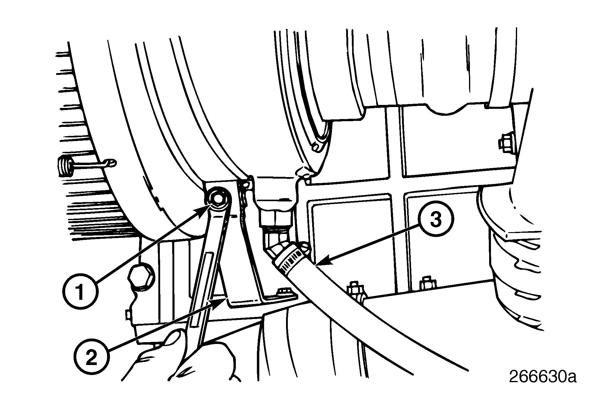
5.Attach the blow-by recirculation unit (AIRSEP®) to the lower support bracket by installing the retaining bolt and tightening to specification. Reconnect the oil drain back hose and clamp.
3. Inlet Tube to Aftercooler Hose Clamps
4.Install the blow-by recirculation unit (AIRSEP®) onto the rear of the engine by connecting the hose to the turbocharger compressor inlet. Place hose clamp in position and tighten to specifications.
1. Blow-By Recirculation Unit (AIRSEP®) Support Bracket Fastener
2. Blow-By Recirculation Unit (AIRSEP®) Bracket
3. Oil Drain Back Hose
6.Reattach the aftercooler air outlet tube by sliding the hose section onto the aftercooler fitting, then sliding the other end over the intake manifold fitting. Tighten hose clamps to specification.
7.Reconnect the outlet hose at the raw water pump and tighten clamp to specification.
8.Open the engine sea water seacock.


