2 minute read
REPAIR INSTRUCTIONS


Cylinder Sleeve Removal
SPECIAL TOOL REQUIRED r Cylinder Liner/Sleeve Puller PT6435
Refer to Figure 156 and Figure 157.
1.Rotate engine in stand so that it is upright (deck surface upward).
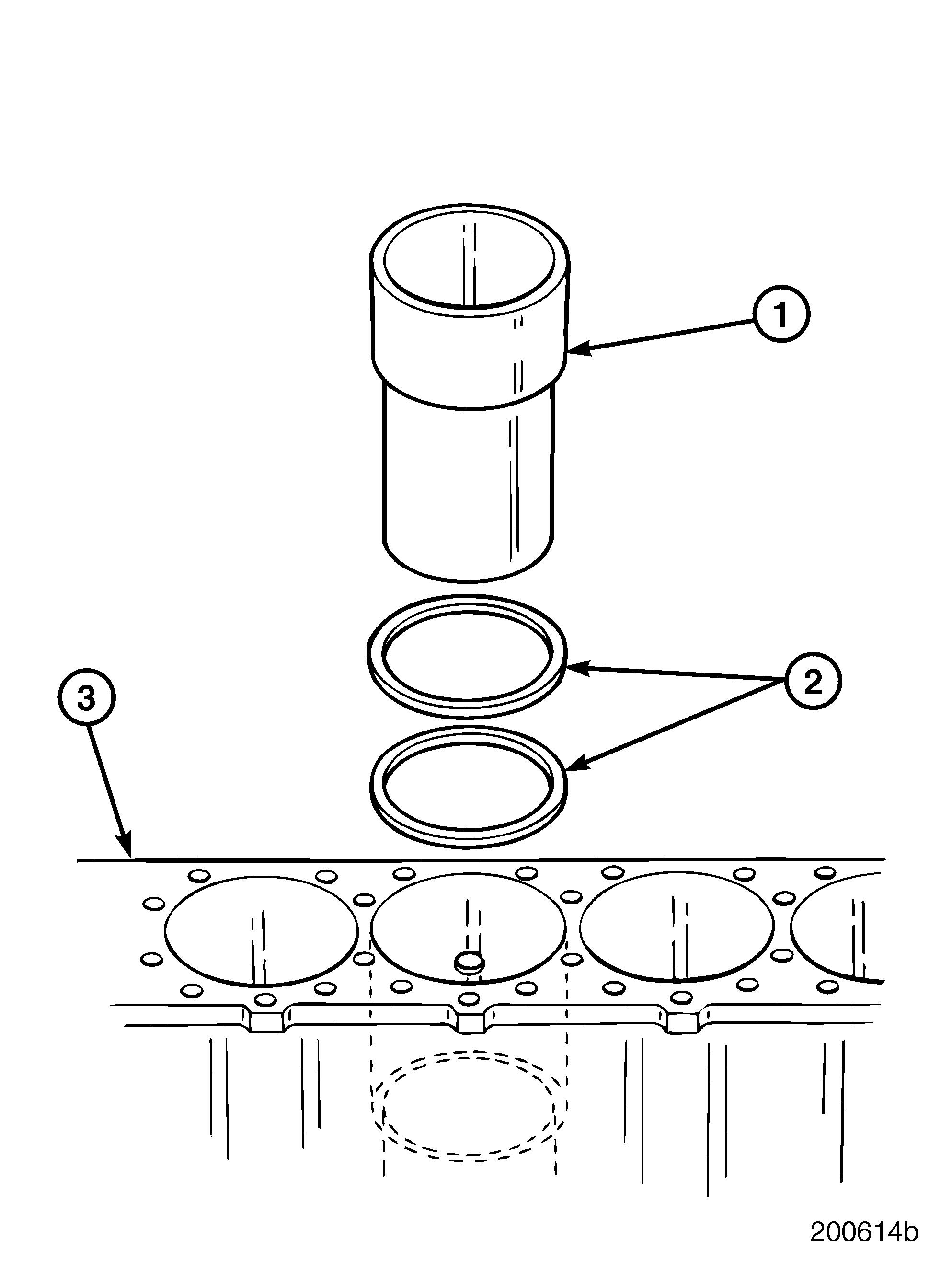
2.Use puller PT6435, or equivalent, to remove cylinder sleeve (1) from cylinder block (3).
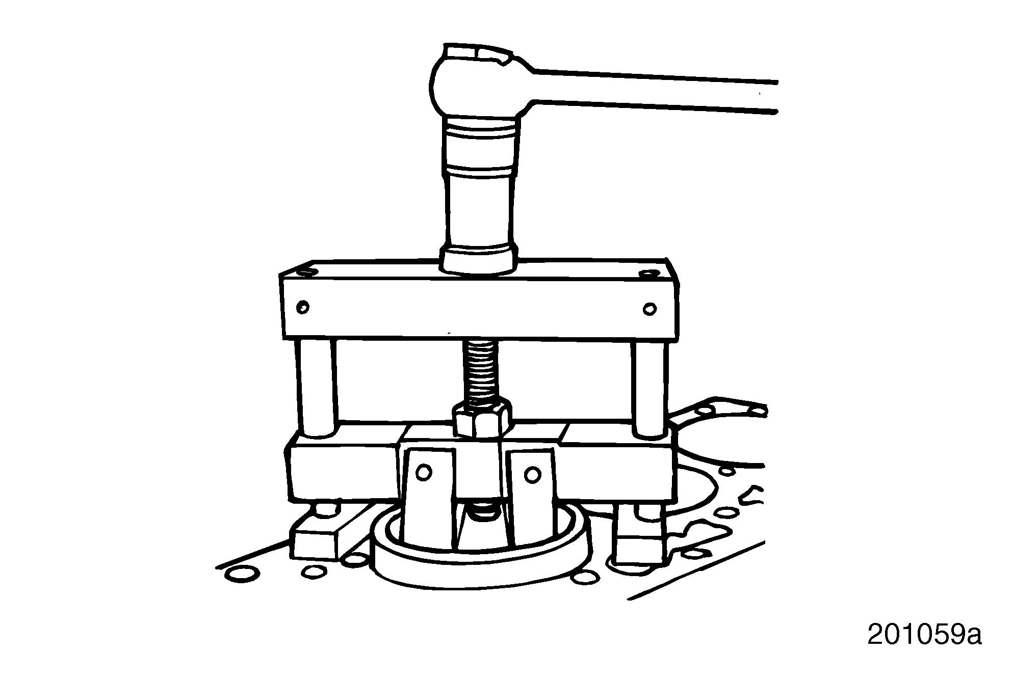
3.Position puller above the sleeve and guide the puller shaft through the sleeve.
Extreme care must be taken to make sure the puller shoe is properly aligned in the bottom of the sleeve to prevent damage to the block.
4.Position puller shoe so that it catches the lower lip of the sleeve. Ensure that it does not extend beyond outside edges of the sleeve, to prevent contact with the cylinder block as the sleeve is removed.
5.Tighten screw on the puller until sleeve comes free from cylinder block bore. Remove shims (2), if installed.
6.Remove puller from sleeve.
7.Repeat steps 2 through 7 to remove remaining cylinder sleeves.
Repair Instructions
Cylinder Sleeve Counterbore Repair
SPECIAL TOOLS REQUIRED r Counterbore Tool PT2210 r Counterbore Cutter Plate PT2210-3A r Universal Dial Depth Gauge PT5025 r Stylus Extension (3-Inch) PT5052-11 r Hex Key Wrench PT2210-14
INSPECTION AND REPAIR
If the cylinder block deck is resurfaced, the cylinder sleeve counterbore depth must be recut to specification. If the cylinder block deck was not resurfaced but cylinder sleeve counterbore surface shows excessive pitting or erosion, recut the counterbore as required.
Use shims to re-establish the correct liner flange height. Shims are available in the following thicknesses: 0.002, 0.003, 0.004, 0.008, 0.010, 0.012 and 0.014 inch.
To resurface the cylinder sleeve counterbore area of the cylinder block, use counterbore tool PT2210 with counterbore cutter plate PT2210-3A.
Do not cut seats deeper than 4.034 inches (102.464 mm).
1.Make sure that the top of the deck is clean and free of burrs. Use a finish mill file and crocus cloth, if necessary, to create a smooth, flat surface for positioning the tool.
2.Using compressed air, thoroughly remove all debris.
Universal dial depth gauge PT5025, with a 3-inch stylus extension PT5052-11, is recommended for measuring the counterbore.
3.Measure and record the counterbore in four places, 90 degrees apart. Using a depth gauge with a 3-inch extension, mark the shallowest point. Subtract the lowest number from the highest number. This is the minimum amount to be machined for cleanup.
SETTING UP COUNTERBORE TOOL PT2210 WITH CUTTER PLATE PT2210-3A
Refer to Figure 158.
1.Loosen the two cutter bit hold-down capscrews (9). Install cutter bit (11) into cutter plate PT2210-3A (13) by turning the cutter bit adjuster (10) counterclockwise. Cutter bit face must be facing a clockwise rotation cut.
Do not tighten the cutter bit hold-down cap (12). The cutter point should not extend beyond the outer edge of the cutter plate. If the cutter bit does stick out, damage to the bit will occur when installing counterbore tool onto cylinder block.
2.Install the cutter plate on the main shaft (15). Use the large end of hex key wrench PT2210-14 (18) to hold the cutter plate and tighten securely. The hole in the side of the cutter plate accepts the large end of the tool.
Do not allow the cutter bit (11) to touch the cylinder sleeve bore wall.
When the entire block must be counterbored, cut the deepest bores first. This way, the tool can be adjusted to the lowest depth and used for all cylinders, ensuring uniform depth on all cylinder counterbores.
3.Position the tool in the cylinder bore by backing off the depth-set collars (5 and 16) and lowering the cutter plate (13) into the counterbore to center the tool.
4.Secure the cutter plate to the cylinder block with four M16 x 2 x 90 hex-head capscrews (3) and special washers (4) from the counterbore tool kit PT2210.
5.Cross-torque the capscrews to 30 lb-ft (41 N•m) using torque wrench J 24406, or equivalent.
Page 123


