5_108.bk Page 181 Thursday, October 4, 2001 11:45 AM
REPAIR INSTRUCTIONS LUBRICATION SYSTEM COMPONENTS INSPECTION
exits the oil cooler through the oil outlet port, flows through the oil filters, and then into the engine.
Oil Cooler Assembly Inspection and Repair
This engine features a “removable-bundle” type oil cooler. Periodic visual inspection of the oil cooler will indicate condition of gaskets, O-ring and core. If a problem exists, these components can be serviced separately rather than replaced as an assembly.
DESCRIPTION The oil cooler assembly is located near the left front of the engine. Engine coolant from the heat exchanger flows through the lower tube and hose assembly, into a chamber in the oil cooler. The coolant then flows into the water pump. The oil pump sends engine oil through the inlet port of the oil cooler into the cooling chamber. Heat from the engine oil is transferred through the chamber walls to the engine coolant. Cooled oil
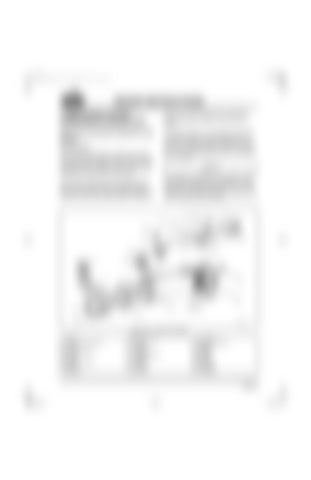
The presence of engine oil in the engine coolant may indicate internal engine problems or worn, loosened or damaged parts within the oil cooler. Continued operation under these conditions may result in severe engine damage. 239
Figure 239 — Oil Cooler Assembly 1. Gasket 2. Coolant Outlet End cap 3. O-Ring 4. Mounting Flange 5. Clamps 6. Coupler 7. Gasket or O-Ring 8. Washer 9. Capscrew
10. Oil Outlet Tube 11. O-Ring 12. Capscrew 13. Washer 14. Oil Supply Head 15. Capscrew 16. Washer 17. O-Ring 18. Pipe Plug
19. Capscrew 20. Coolant Inlet Cap 21. Gasket 22. Bundle 23. Gasket 24. Housing 25. Gasket 26. Capscrew 27. Capscrew
Page 181


