5_108.bk Page 152 Thursday, October 4, 2001 11:45 AM
REPAIR INSTRUCTIONS Pistons
DISASSEMBLY
DESCRIPTION
Refer to Figure 195.
A two-piece piston is required to aid in particulates control. To ensure a high level of durability, the piston crown is made from forged steel and the piston skirt is made of cast aluminum. The piston pin bore pedestal and piston skirt are stamped FRONT, and must be facing front of engine.
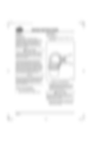
1. Using piston ring expander PT6587, remove piston rings. 195
A radius is cut in lower edge of piston skirt to provide clearance for piston cooling nozzle. The piston must be installed with the word FRONT facing front of engine. The two-piece piston design incorporates two compression ring grooves and one oil ring groove. A plasma-faced, keystone-type ring is used in the top ring location. A tapered chrome, rectangular-type ring is used in the second ring groove. The oil control ring is located in the third (or lower) groove, nearest the piston pin bore. Piston rings are designed to improve oil control, especially relating to particulates control.
Piston crowns have no oil drainback holes. They have been replaced by an oil accumulator relief. The relief is machined into the lower half of the third ring land face, 360 degrees around the piston circumference.
SPECIAL TOOLS REQUIRED r
Piston Ring Expander PT6587
r
Keystone Ring Groove Gauge J 29510
Figure 195 — Piston Ring Removal
2. Thoroughly clean ring grooves and combustion bowl area. All carbon must be removed. Carbon left in grooves will reduce ring clearance and prevent replacement rings from seating properly.
Be sure that cleaning solvent is approved for steel/aluminum. Incompatible solvent may cause damage to pistons or skirts. 3. Clean pistons with approved solution and a brass brush. Take care to avoid damaging pistons while cleaning.
Page 152


