5_108.bk Page 115 Thursday, October 4, 2001 11:45 AM
REPAIR INSTRUCTIONS Auxiliary Driveshaft Removal Refer to Figure 144. 1. Remove auxiliary driveshaft gear retaining nut (1). 2. Using a hub puller such as J 21834-4A, or equivalent, remove auxiliary driveshaft gear (2) from the splines (5) on the end of shaft.
4. Remove the auxiliary driveshaft (3) by pulling it rearward out of the raw water pump mounting flange opening. With engine oil pump in position, a rotating motion may be necessary to clear the engine oil pump drive gear (6). 145
3. Remove two retaining capscrews (3) from auxiliary driveshaft captured thrust washer (4). Remove washer. 144
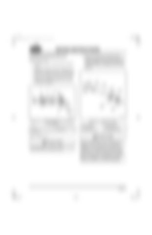
Figure 144 — Auxiliary Driveshaft Gear and Captured Thrust Washer 1. Nut 2. Auxiliary Driveshaft Gear 3. Capscrew
4. Captured Thrust Washer 5. Shaft Splines
Figure 145 — Auxiliary Driveshaft 1. Rear Bushing 2. Front Journal 3. Auxiliary Driveshaft
4. Rear Journal 5. Oil Metering Plug 6. Oil Pump Drive Gear
Refer to Figure 145.
Avoid damaging the auxiliary driveshaft bushings or journals while removing the shaft.
Note the oil feed hole in the oil metering plug at the rear of the auxiliary shaft. If this hole is plugged up, the raw water pump may fail from oil starvation. Also, the loss of oil pressure that results from a missing plug can cause damage and problems in other components and parts. Make sure the plug is not missing or the metering hole is not plugged. If replacing the auxiliary driveshaft, make sure to install a new plug.
Page 115


