Cat 3508 Diesel Engine Service Manual

Page 41

3500 ENGINE

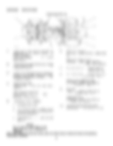
SPECIFICATIONS TURBOCHARGER C153

(1)

(2)

(3)

(4)

Torque for the bolts and nuts that hold the turbocharger to the exhaust manifold (put 5P3931 Anti-Seize Compound on threads)................. 270 ± 25 N-m (200 ± 18 lb. ft.) Torque for the bolts that hold the turbine housing to the cartridge housing........................... 48 ± 3 N•m (35 ± 2 lb. ft.) Torque for the bolts that hold the compressor housing to the cartridge housing (put 5P3931 Anti-Seize Compound on the threads) ......... 25 ± 5 N-m (18 ±4 lb. ft.) Width of oil seal ring at compressor end........2.500 ± 0.010 mm (.0984 ± .0004 in.)

(6)

Width of oil seal ring groove at turbine end ......2.550 + 0.030 - 0.010 mm (.1004 + .0012 - .0004 in.) (7)

End play for the shaft ...... 0.090 to 0.130 mm (.0035 to .0051 mm)

(8)

Bore in the bearings...... 24.020 +0.010-0.0mm (.9457 + .0004 - .00 in.) Diameter of the surfaces (journals) on the shaft ......24.000 + 0.0 - 0.009 mm (.9449 + .00 - .0004 in.)

(9)

Width of oil seal ring groove at compressor end............................ 2.635 ±0.035 mm (.1037 ± .0014 in.) (5)

Put impeller on the shaft.

b.

Put a small amount of 2P2506 Thread Lubricant on the threads and impeller face that will be under the nut.

c.

Tighten the nut to.................. 95 ±5 N-m (70 ±4 lb. ft.)

Bore in the housing ........32.000 + 0.016 - 0.0 mm (1.2598 + .0006 - .00 in.) Outside diameter of the bearings ....31.890 + 0.0 - 0.010 mm (1.2555 + .00 - .0004 in.)

Turbocharger impeller installation: a.

Width of oil seal ring at turbine end ......2.500 ± 0.010 mm (.0984 ±.0004 in.)

(10)

Torque for the three bolts that hold the thrust bearing ......... 10 ± 2 N•m (7 ±1 lb. ft.)

NOTICE Do not bend or add stress to the shaft when the nut Is loosened or tightened. NOTE: FOR TORQUE VALUES NOT GIVEN, SEE THE FIRST PAGE OF SPECIFICATIONS FOR GENERAL TIGHTENING TORQUES 21


Turn static files into dynamic content formats.

Create a flipbook

Articles inside

Pistons

3min
pages 396-397

Spacer Plates

2min
pages 391-392

Front Balancer Group

1min
pages 385-386

Crankshaft Main Bearings

4min
pages 393-395

Rear Gear Group

3min
pages 387-390

Connecting Rod Bearings

1min
page 384

Bridge Dowels

2min
pages 382-383

Cylinder Heads

4min
pages 377-380

Fuel Injectors

3min
pages 369-370

Valves

1min
page 381

Valve Covers

1min
page 365

Rocker Shafts and Push Rods

4min
pages 366-368

Fuel Injection Control Linkage

6min
pages 371-376

Flywheel Housing

1min
pages 363-364

Flywheel

1min
page 362

Crankshaft Front Seal and Wear Sleeve

2min
pages 354-355

Crankshaft Rear Seal and Wear Sleeve

2min
pages 356-357

Front Drive Housing

4min
pages 358-361

Oil and Water Pump Drive

1min
pages 350-352

Crankshaft Vibration Damper

1min
page 353

Accessory Drive (Front

1min
pages 347-349

Hydramechanical Shutoff Drive

1min
pages 345-346

Hydramechanical Shutoff Control

12min
pages 332-344

Governor Drive

3min
pages 328-331

Governor

1min
pages 326-327

Exhaust Manifolds

1min
page 321

Aftercooler

2min
pages 322-325

Turbochargers

6min
pages 312-320

Oil Cooler

4min
pages 305-311

Oil Sequence Valves

1min
page 304

Oil Pan

2min
pages 300-303

Oil Filter Housing

5min
pages 293-299

Oil Pump

5min
pages 288-292

Fuel Priming Pump, Fuel Transfer Pump

4min
pages 283-287

Fuel Filter Housing

3min
pages 279-282

Water Pump

2min
pages 275-278

Water Temperature Regulators

1min
pages 272-274

Gauge Panel

6min
pages 259-261

Crankcase Breather

1min
pages 270-271

Wiring Diagrams

9min
pages 247-252

3500 Industrial Engines

6min
pages 253-256

Manual Shutoff

3min
pages 257-258

System Checks

1min
pages 243-244

Troubleshooting

4min
pages 239-242

Hydraulic Circuits, Later with an Alarm System

6min
pages 232-238

Hydraulic Circuits (Later

5min
pages 228-231

Electrical Switches

1min
page 210

Air Intake Shutoff

5min
pages 206-208

Shutoff Control Group

6min
pages 199-201

3500 Series Engines

4min
pages 197-198

Auxiliary Controls

2min
pages 192-196

Governor Preparation

3min
page 181

Governor Installation

8min
pages 182-186

Pneumatic Speed Setting Control Troubleshooting

3min
pages 178-179

Air Fuel Ratio Control Troubleshooting

7min
pages 176-177

Pneumatic Mid Speed Control

5min
pages 170-171

Air Fuel Ratio Control

4min
pages 167-168

Pneumatic Speed Control

3min
pages 165-166

Operation of the 3161 Governor

6min
pages 161-163

Governor Types

4min
pages 157-158

Caterpillar, 3161 Governor

2min
pages 155-156

Vibration Damper

1min
page 149

Starting System Air Starting System...................................Deleted

4min
pages 152-154

Checking Crankshaft Deflection (Bend

1min
page 148

Flywheel and Flywheel Housing

4min
pages 146-147

Water Temperature Regulator Test

2min
page 144

Pressure Cap Test

1min
page 142

Valve Clearance

3min
pages 137-138

Clearance Setting

2min
page 136

Air Fuel Ratio Control

1min
page 132

Bridge Adjustment Crankshaft Positions for Valve

2min
page 135

Fuel Setting Adjustment

2min
page 126

Engine Speed Measurement

2min
page 127

Fuel Setting

2min
page 125

Injector Synchronization

2min
pages 123-124

Startup Procedure

1min
page 120

Fuel Timing

1min
page 122

Camshaft Timing

2min
pages 118-119

Fuel Pressure

1min
page 116

Injector Test Sequence

9min
pages 110-115

Air Starting System

4min
pages 86-87

Leak Test for Injector Tester

1min
page 109

Contactor Switch (Water Temperature

4min
page 90

Camshafts

1min
page 85

Air Fuel Ratio Control

1min
pages 73-74

Woodward UG8 Lever Governors

2min
pages 71-72

Fuel Injector

2min
pages 68-70

Fuel Injection Control Linkage

1min
page 67

Engine Design

1min
pages 63-64

Fuel System

3min
pages 65-66

Systems Operation, 3500 Industrial Engines

1min
pages 61-62

Flywheel Housing Runout Alternators and Regulators.......................Deleted

11min
pages 53-60

Flywheel Housing Bore

1min
page 52

Rear Gear Group

2min
pages 45-46

Flywheel

1min
page 47

Upper Front Gear Group (7N4871

1min
page 44

Lower Front Gear Group

2min
pages 42-43

Front Balancer Group (3508

1min
page 41

Crankshaft Wear Sleeves and Seals

1min
page 40

Connecting Rod and Main Bearing Journals

1min
page 38

Pistons and Rings

1min
page 36

Crankshaft

1min
page 39

Water Pump

1min
page 31

Cylinder Block

1min
page 34

Oil Cooler Bypass and Cooling Jet Sequence Valves

1min
page 30

Oil Filter Bypass Valve (Earlier

1min
page 28

Air Intake Shutoff

1min
pages 23-25

and Taperlock Studs

5min
pages 3-4

Fuel Injection Control Group

3min
page 10

Oil Pump

1min
pages 26-27

Camshafts

3min
pages 12-13

Oil Filter Bypass Valve (Later

1min
page 29

Engine Design

5min
pages 5-7
Issuu converts static files into: digital portfolios, online yearbooks, online catalogs, digital photo albums and more. Sign up and create your flipbook.
Cat 3508 Diesel Engine Service Manual by www.heydownloads.com - Issuu