
5 minute read
Pneumatic Mid Speed Control


2. Cables between the battery, starter and engine ground must be the correct size. Wires and cables must be free of corrosion and have cable support clamps to prevent stress on battery connections (terminals).
3. Leads, junctions, switches and panel instruments that have direct relation to the charging circuit must give correct circuit control.
Advertisement
4. Inspect the drive components for the charging unit to be sure they are free of grease and oil and have the ability to operate the charging unit.
Alternator Regulator Adjustment (Delco-Remy)
When an alternator is charging the battery too much or not enough, an adjustment can be made to the output voltage of some alternators. Make reference to the SPECIFICATIONS section to find all testing specifications for the alternators and regulators.
Delco-Remy 24V 60A (4N3986 Alternator)
No adjustment of voltage output can be made on this alternator. If the voltage and ampere output is not correct, the alternator must be repaired or replaced.
Delco-Remy 32V 60A (4N3987 Alternator)
To make an adjustment to the voltage output, pull out voltage adjustment cap (1). Turn the cap 90° and install it again into the alternator. The voltage adjustment cap has four positions: HI, LO, and two positions between the high and the low setting.
The 4N3987 Alternator can be adjusted for either 30 or 32 volts. A replacement alternator shipped from the factory will be adjusted for 32V (16 battery cells) systems. Where the alternator is to be used in a 30V (15 battery cells) system, pull out voltage adjustment cap (1) and change from the HI position to position 3.
CAP TYPE REGULATOR ADJUSTMENT
152
1. Voltage adjustment cap.
No adjustment can be made to change the rate of charge on these alternator regulators. If the rate of charge (ampere output) is within 10 amperes of rated output (marked on the alternator frame) the regulator is good. An over or under charged battery condition can be corrected sometimes by an adjustment to the voltage. If rate of charge is not correct, a replacement of the regulator is necessary.
Alternator Pulley Nut Tightening (Delco-Remy)
Tighten nut that holds the pulley to a torque of 100 ± 10 N m (75 Z± 5 lb. ft.) with the tools shown.
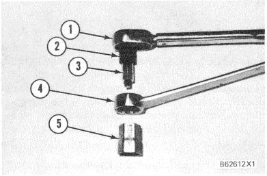
TOOLS TO TIGHTEN ALTERNATOR PULLEY NUT 1. 5P7425 Torque Wrench. 2. 8S1588 Adapter (1/2" female to 3/8" male). 3. FT1697 Socket. 4. 8H8517 Combination Wrench (1 1/8"). 5. FT1696 Wrench.
STARTING SYSTEM
Use the multimeter in the DCV range to find starting system components which do not function.
Move the start control switch to activate the starter solenoid. Starter solenoid operation can be heard as the pinion of the starter motor is engaged with the ring gear on the engine flywheel.
If the solenoid for the starter motor will not operate, it is possible that the current from the battery did not get to the solenoid. Fasten one lead of the multimeter to the connection (terminal) for the battery cable on the solenoid. Put the other lead to a good ground. A zero reading is an indication that there is a broken circuit from the battery. More testing is necessary when there is a voltage reading on the multimeter.
The solenoid operation also closes the electric circuit to the motor. Connect one lead of the multimeter to the solenoid connection (terminal) that is fastened to the motor. Put the other lead to a good ground. Activate the starter solenoid and look at the multimeter. A reading of battery voltage shows the problem is in the motor. The motor must be removed for further testing. A zero reading on the multimeter shows that the solenoid contacts do not close. This is an indication of the need for repair to the solenoid or an adjustment to be made to the starter pinion clearance.
Make a test with one multimeter lead fastened to the connection (terminal) for the small wire at the solenoid and the other lead to the ground. Look at the multimeter and activate the starter solenoid. A voltage reading shows that the problem is in the solenoid. A zero reading is an indication that the problem is in the start switch or the wires for the start switch.
Fasten one multimeter lead to the start switch at the connection (terminal) for the wire from the battery. Fasten the other lead to a good ground. A zero reading indicates a broken circuit from the battery. Make a check of the circuit breaker and wiring. If there is a voltage reading, the problem is in the start switch or in the wires for the start switch.
A starter motor that operates too slow can have an overload because of too much friction in the engine being started. Slow operation of the starter motor can also be caused by a short circuit, loose connections and/or dirt in the motor.
Pinion Clearance Adjustment
When -the solenoid is installed, make an adjustment of the pinion clearance. The adjustment can be made with the starter motor removed.
1. Install the solenoid without connector (1) from the MOTOR connections (terminal) on solenoid to the motor.
2. Connect a battery, of the same voltage as the solenoid, to the terminal (2), marked SW.
3. Connect the other side of the battery to ground terminal (3). CONNECTION FOR CHECKING PINION CLEARANCE 1. Connector from MOTOR terminal on solenoid to motor. 2. SW terminal. 3. Ground terminal.

4. Connect for a moment, a wire from the solenoid connection (terminal) marked MOTOR to the ground connection (terminal). The pinion will shift to crank position and will stay there until the battery is disconnected.
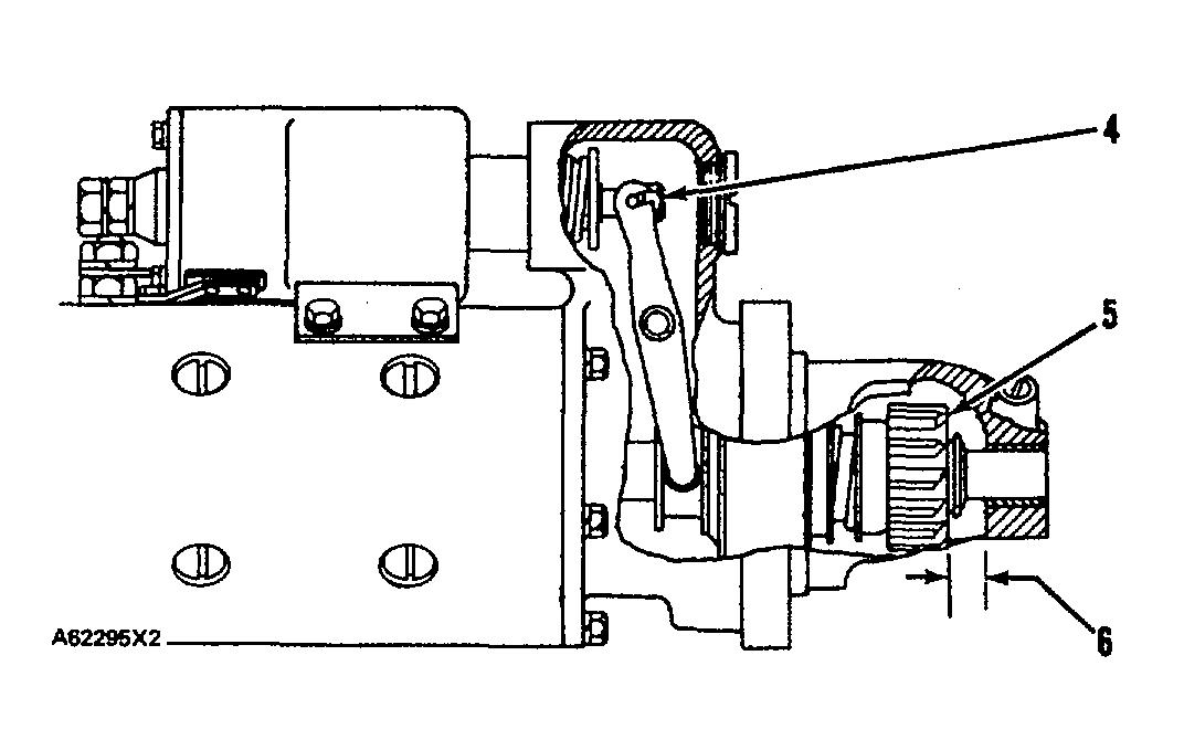
PINION CLEARANCE ADJUSTMENT 4. Shaft nut. 5. Pinion. 6. Pinion clearance.
5. Push the pinion toward the commutator end to remove free movement.
6. Pinion clearance (6) must be 8.4 to 9.9 mm (.33 to .39 in.).
7. To adjust pinion clearance, remove plug and turn nut (4).


