8 minute read
Governor Installation


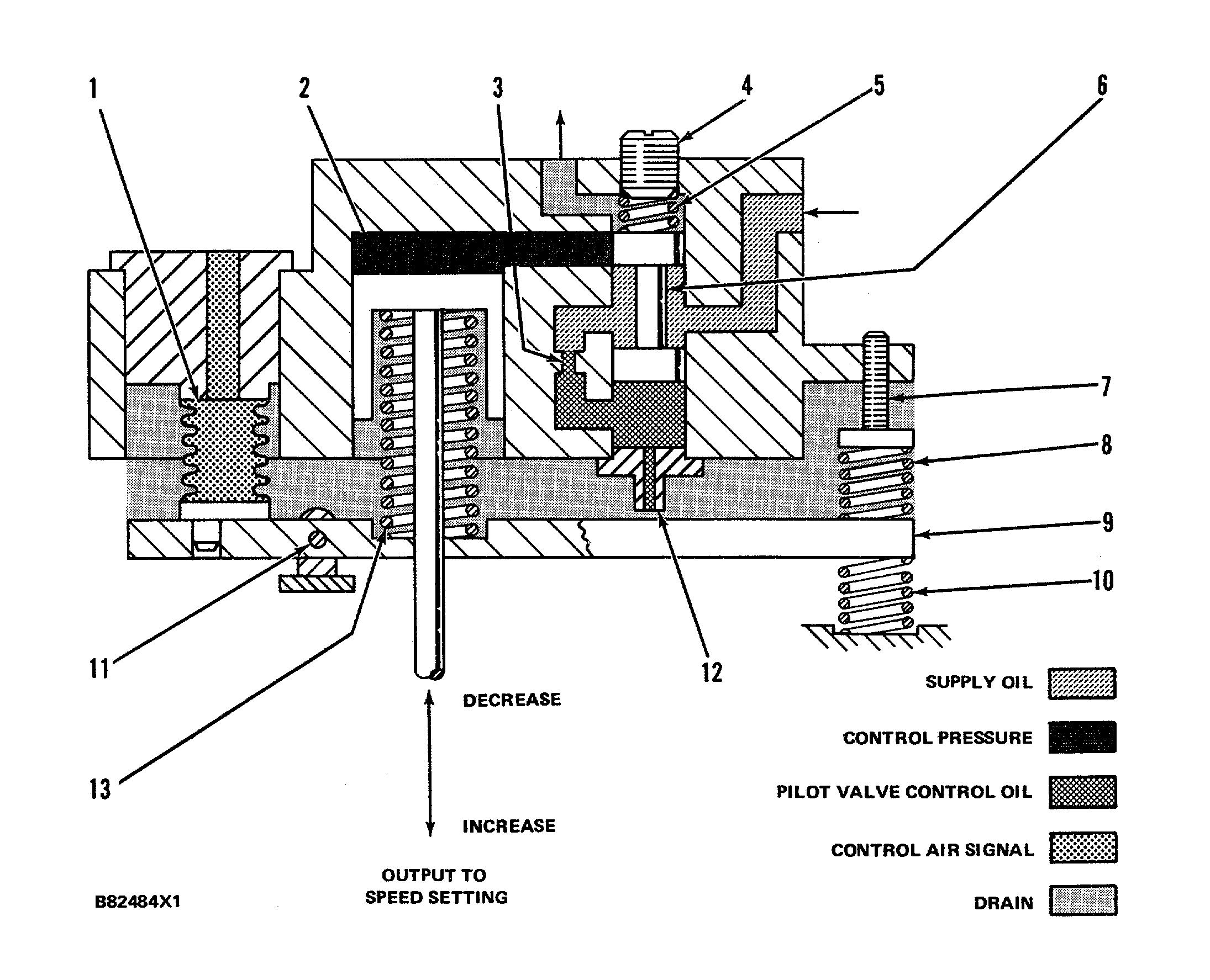
PNEUMATIC SPEED SETTING CONTROL SCHEMATIC
1. Speed setting bellows. 2. Speed setting piston. 3. Orifice. 4. Spring seat. 5. Pilot valve loading spring. 6. Speed setting pilot valve plunger. 7. Base speed adjusting screw. 8. Upper speed setting bias spring. 9. Speed setting lever. 10. Lower speed setting bias spring. 11. Pivot. 12. Nozzle. 13. Feed-back spring.
Advertisement
166
AIR FUEL RATIO CONTROL
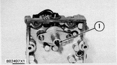
3161 GOVERNOR WITH AN AIR FUEL RATIO CONTROL 1. Air fuel ratio control.
The air fuel ratio control assembly (1) is installed on the right rear corner of the top cover. The control is factory calibrated and installed. This control is not for field installation.
The air fuel ratio control is similar to hydraulic air fuel ratio controls used on current Caterpillar engines. This control automatically controls the governor output shaft movement in the "fuel increase" direction, until air pressure in the engine inlet manifold is high enough to give complete fuel combustion.
The air fuel ratio control limits the fuel to the engine in proportion to the amount of turbocharger boost pressure (pressure above atmospheric) in the inlet manifold. The control is not activated during engine start up and is cocked (activated) by a combination of oil pressure and the initial surge of boost when the engine is first loaded.
Engine Start Up
As the engine is started and the speed or load is increased, air pressure from the inlet manifold increases and pushes up on the rolling diaphragm assembly to put the limiter spring under compression. As the rolling diaphragm assembly moves up, the fuel limiter plunger also moves up and closes off the port in the limiter piston. Now the supply oil can not drain through the limiter piston and the pressure of the oil starts to increase. When the oil pressure is high enough, the limiter piston is pushed down against the limiter servo spring force. The lower edge of the fuel limiter plunger opens the port in the limiter piston when the piston has moved down far enough. This lets supply oil go to drain. The air fuel ratio control is now activated and can operate as needed.
167 Engine Load Increases
As more load is put on the engine, the air pressure in the inlet manifold is increased. The increased air pressure pushes the rolling diaphragm assembly up and lifts the fuel limiter plunger more. Oil pressure on the limiter piston decreases as the limiter piston drain port is opened and the limiter piston moves up until the port is closed again. At this time the limiter piston is stopped in a new position that is proportional to the air pressure in the inlet manifold.
Now, with the engine in operation at a steady speed, load added decreases engine speed. The governor moves to increase fuel as the power piston moves up to turn the output shafts in the "increase" direction. As the output shafts turn, the right end of the limit floating lever is lifted. Because the limit floating lever is fastened to a pivot (pivot position is set by the air fuel ratio control), the left end of the lever pushes the limit/shutdown rod down. The limit/shutdown pilot valve plunger closes off governor control oil to the power piston and limits the power piston movement.
As the engine picks up load, air pressure to the air fuel ratio control increases. The rolling diaphragm assembly moves up and lifts the fuel limiter plunger which opens the port in the limiter piston. Oil pressure on the limiter piston is lowered, and lets the limit servo spring push the piston and output rod up. This lets the limit/shutdown pilot valve move up. Fuel limit level is then increased.
NOTE: The air fuel ratio control fuel limit range is set by the position of the limit cam on the limit lever. When the cam is moved away from the shutdown rod, the limit range is longer. When the cam is moved closer to the shutdown rod, the limit range is shorter.
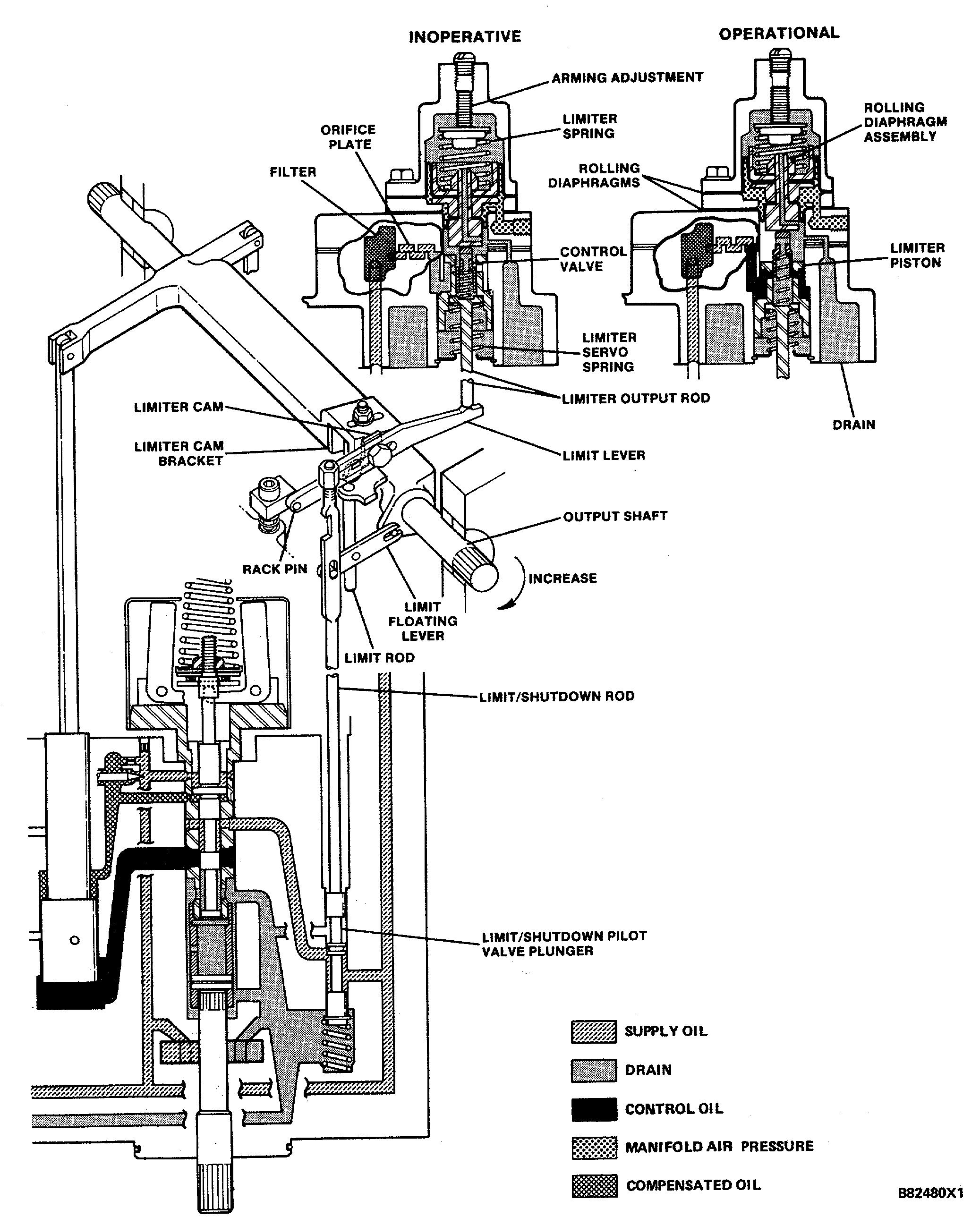
SCHEMATIC OF AIR FUEL RATIO CONTROL ON THE 3161 GOVERNOR
168
SPEED ADJUSTING MOTOR GOVERNOR HEAD

3161 GENERATOR SET GOVERNOR 1. Conduit connection. 2. Speed adjusting meter. 3. Electric shutdown assembly.
The speed adjusting motor governor head includes a 24/32 Volt DC remote control speed adjusting motor (2) for changing engine speeds from remote locations. The speed adjusting motor is installed on the governor top cover and is connected to the governor speed setting mechanism through a friction clutch. The motor drives through the friction clutch and rotates the speed adjusting screw to position the governor’s speed adjusting lever. The governor set speed may be increased or decreased at the rate of 13 rpm/ second. One revolution of the manual adjusting screw will increase engine speed 63 rpm (approximately).
To increase the speed setting, the motor shaft rotates clockwise. As the motor shaft rotates, it turns the speed adjusting screw to make contact with the speed adjusting lever and lowers it to increase the governor’s speed setting. The motor shaft turns the speed adjusting screw until the speed adjusting lever contacts the high speed stop. If the motor continues to run, the clutch will slip to prevent damage to the motor.
NOTICE The motor should not be left running with the clutch slipping, or clutch wear will occur. To decrease speed setting, the motor shaft turns counterclockwise and the speed adjusting screw backs out, allowing the speed adjusting lever to move to the "decrease speed" setting.
If the motor shaft is permitted to rotate counterclockwise after the speed adjusting lever has reached the low speed stop screw, the speed adjusting screw will turn out to the maximum position. The clutch will then slip until the motor is stopped.
169
NOTE: If the speed adjusting motor has been allowed to run after the low speed setting has been reached, it may take a period of time for the speed adjusting screw to turn in and make contact with the speed adjusting lever (when an increase in speed setting is required).
All wiring and power to the remote speed setting motor on the governor must be low voltage DC. A converter drop box which will convert 115 or 230 volt AC (50 to 60 Hertz) to 24 volt DC is available (2W4523). This box should be remote mounted from the engine to isolate the engine wiring harness from high voltage AC currents.
An internal one-half inch thread conduit connection (1) is on top of the governor cover. It is used for installations which require conduit protection for the wiring.
The top governor cover is made for installation of any of the three shutdown assemblies.
MANUAL SPEED SETTING CONTROL

3161 GENERATOR SET GOVERNOR
The manual speed setting control is located on the front of the speed adjusting motor governor head. Engine speed is set manually as the speed setting screw is turned. The high and low idle stops limit the speed range.
TOP COVER OF THE 3161 GENERATOR SET GOVERNOR 1. Speed adjusting screw.
An indicator lever is attached to the governor speed setting shaft with a bolt. The bolt can be loosened and the indicator lever can be set to the reference points on the identification and information plate to correspond with the number on the dial. The indicator lever will show the speed setting before the engine is started.
The manual speed setting control and the speed adjusting motor use a common speed adjusting screw which contacts the governor speed adjusting lever.
The speed adjusting motor clutch is above the gear and connects the motor to the speed adjusting screw. This clutch keeps force off of the speed adjusting motor as the speed setting is adjusted manually.
MANUAL MECHANICAL SPEED CONTROL
3161 GOVERNOR 1. Shaft. 2. Handle assembly. 3. Guide. 4. Hub. 5.
Quadrant. 6. Ratchet mounting plate. .70 SYSTEMS OPERATION The manual mechanical speed control with remote and positive lock is available for torque rise and non-torque rise equipped governors. The control is used for manually setting different ~,_ engine speeds, or it can be used as a remote speed control.
The shaft (1) goes through the handle assembly (2) and is threaded into the hub (4) on the spline of the speed setting shaft. The guide (3) rotates on the speed setting shaft and supports the handle assembly. The ratchet mounting plate (6) is bolted to the front of the governor and has notches to hold the handle for different engine speeds. The quadrant (5) can be engaged with the handle assembly and used as a mechanical linkage to the speed setting shaft.
A cable or rod can be connected to the quadrant and used for remote speed control.
To increase or decrease engine speed, push on the shaft and lift on the handle assembly. This disengages the handle assembly from the ratchet mounting plate. The control can then move the speed setting shaft. Movement of the handle in the clockwise direction increases the engine speed.
To disengage the handle assembly from the ratchet and connect the quadrant, push on the shaft and lift on the handle assembly. With the handle assembly raised, turn it 180 degrees and connect it to the quadrant. The control can now be used for remote operation.
NOTE : The manual mechanical speed control with remote and positive lock should not be used with a pneumatic speed control. Vibration can cause the manual mechanical speed control to engage and stop pneumatic speed control operation.
PNEUMATIC MID SPEED CONTROL A pneumatic speed control is normally used on 3161 Governors on vehicular engine arrangements to control the engine speed. A pneumatic mid speed control is also used to make the engine go from low idle to mid speed for dynamic braking with the direct current generator and drive motors.
This control is installed on the front of the governor. With a lever fastened to the speed setting " control shaft, the control cylinder sets the engine speed from low idle to mid speed. The mid speed setting of the governor is set by the position the control lever is fastened to the speed setting control shaft.


