4 minute read
Cylinder Heads


FLYWHEEL HOUSING
INSTALL FLYWHEEL HOUSING1157-12
Advertisement
Tools Needed A 5P9736 Link Bracket 2
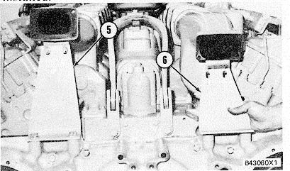
1. Install O-ring seal (1) on the engine block and put clean engine oil on it. 2. Put the flywheel housing gasket in position on the rear of the engine block. 3. Install two 5/8"-11 NC guide bolts (2) in the, engine block. 4. Fasten a hoist to flywheel housing (3) with_43056 tooling (A) and put the housing in position on the guide bolts. Install the bolts to hold the housing in position and tighten the bolts evenly. Remove the guide bolts and install the remainder of the bolts. 5. Cut the flywheel housing gasket even with the bottom of the cylinder block.-!_w 6. Fasten a hoist to the engine and lift the engine enough to remove the plates between the cylinder block and the oil pan. If the oil pan gasket is damaged, the engine will have to be removed from the oil pan to make a replacement of the gasket. Lower the engine on the oil pan and 430 remove the guide bolts from the oil pan. Install all of the bolts that hold the oil pan to the engine. 7. Put camshaft drive gears (4) in position on the ends of the camshafts. Install the plate and tachometer drive adapter assembly to hold the gears in position. Tighten the bolts evenly to a torque of 100 + 15 N-m (75 + 11 lb. ft.). Hit the plate and adapter assembly with a hammer3 and tighten the bolts again to the same torque. Do this until the torque does not change. 8. Install brackets (5) and (6) on the engine. NOTE: Any time the rear crankshaft seal and wear sleeve are removed, a new seal and sleeve must be installed.
end by:
a) install exhaust elbow b) install tachometer drive c) install crankshaft rear seal and wear sleeve’
VALVE COVERS, ROCKER SHAFTS AND PUSH RODS
REMOVE VALVE COVERS1107-11
1. Remove bolts (1) and remove valve cover (2) from the valve cover base.
2. If necessary, remove the seal from valve cover, (2).
INSTALL VALVE COVERS 1107-12
1. Make sure seal (I) is installed in the groove of valve cover (3). Cut new seals to fit at assembly.
2. Put valve cover (3) in position on valve cover base (2) and install the four bolts to hold it. Tighten the bolts to a torque of 14 + 3 N•m (10 + 2 lb. ft.).
REMOVE ROCKER SHAFTS AND PUSH RODS 1102 & 1208-11
start by: a) remove valve covers
1. Remove bolts (1) and lift shaft (2) and the rocker arms off the valve cover base and the push rods.
2. Remove push rods (3) from the valve lifters and valve cover base.
365
ROCKER SHAFTS AND PUSH RODS
3. Remove bridge assemblies (4) from the dowels.
INSTALL ROCKER SHAFTS AND PUSH RODS 1102 & 1208-12
1. Loosen the adjustment nuts and screws (1) on valve bridges (2)
2. Put clean engine oil on the bridge dowels, the inside diameter of valve bridges (2) and on the top pad of the valve bridge. Install valve bridges (2) on the bridge dowels as shown.’
3. While bridges (2) are pushed straight down with a force of 25 + 20 N (5.6 + 4.5 lb.) on the top contact surface, turn adjustment screw (1) : until it makes contact with the valve stem. Turn : screw (1) another 200 to 300. This will straighten the dowel in the guide and make compensation for clearance (slack) in the threads.
4. Hold adjustment screw (1) in position and, tighten the nut around screw (I) to a torque of. 30 _ 4 N•m (22 ± 3 lb. ft.).B3797
5. Put push rods (3) in position in the valve lifters and valve cover base.
NOTICE Make sure the crankshaft and camshafts are in time with each other and that adjustment screws (5) are turned all the way out before the rocker shaft bolts are tightened or damaged to, the valves or pistons can be the result. See INSTALL CAMSHAFTS for the procedure to time the engine.
6. Put the rocker arms and shaft (4) in position on the valve cover. Make sure the rocker shafts and push rods are in alignment and install the bolts to hold shaft (4).
7. Make an adjustment of the valves to have a clearance of 0.40 mm (.016 in.) for intake and 0.76 mm (.030 in.) for exhaust. See VALVE CLEARANCE SETTING in TESTING" AND ADJUSTING section for the complete procedure.
a) install valve covers.
366
ROCKER SHAFT ASSEMBLIES
DISASSEMBLE ROCKER SHAFT ASSEMBLIES 1102-15
Tools Needed A 1P510Driver Group 1
start by: a) remove rocker shafts and push rods
1. Slide shaft assembly (1) out of rocker arms (2). If necessary, remove the dowel from shaft assembly (1).
2. Remove adjustment screw (4) and the nut from rocker arm (2).
3. Use a hammer and punch to push socket (3) out( of rocker arm (2).
4 Remove the ring that holds button (5) in socket (3) and remove the button from the socket.
5. Use tool group (A) to remove bearing (6) from rocker arm (2).
6. Do Steps 2 through 5 for the other two rocker arms.


