7 minute read
Air Fuel Ratio Control Troubleshooting


When the pilot valve plunger is lowered, oil under high pressure moves through the control port of the bushing, to the bottom side of the power piston, and the piston moves up. When the pilot valve plunger is raised, the oil from the bottom of the power piston is released to sump, and the higher oil pressure on top of the piston moves the piston down. When the engine is running at a steady state, the control land of the pilot valve plunger covers the ports in the ballhead bushing and the power piston does not move. The movement of the pilot valve plunger is controlled by the ballhead assembly.
Ballhead Assembly
Advertisement
The ballhead system has a ballhead, flyweights, speeder spring, thrust bearing, and speeder plug. The ballhead, as part of the pilot valve bushing, is turned by the drive coupling and drive shaft.
As the ballhead turns, the centrifugal force causes the flyweights to pivot outward. At the same time, the force of the speeder spring pushes the thrust bearing down on the flyweight toes against the centrifugal force of the flyweights. When the speeder plug is pushed down this increases the downward pressure on the speeder spring, and the governor speed setting is increased. The engine then runs at a higher speed and puts a higher centrifugal force on the flyweights to equal the speeder spring force and put the system back in balance.
Speeder spring force or speed setting is controlled through the speed setting shaft.
Compensation System
The compensation system has a needle valve and a buffer piston with two springs. This system can be adjusted to give the desired rate of governor control and engine speed stability. Since the governor makes an adjustment rapidly to a change in engine load or speed setting, the engine can go into a "hunt" condition (temporary increase and decrease in engine speed) if too much adjustment is made. The purpose of the compensation system is to prevent overcorrection to the engine load or speed setting change. The system uses a pressure differential that is applied across the compensation land of the pilot valve plunger to give a stable governor control.
Speed Droop
The 3161 Governor is an isochronous governor with the ability to operate with droop by the adjustment of an internal droop pivot pin. The governor may be used with droop to allow for load division between two or more engines connected to a single shaft, or for operating in parallel.
The speed droop of a governor is the percent that the engine speed drops between high idle and full load. The 3161 Standard and Torque Rise Governors are designed to operate with a 2 to 8 percent droop and have an internal droop pivot pin adjustment.
The 3161 Generator Set Governor is designed to operate with a 0 to 4 percent droop. It has an external adjustment lever connected to the internal droop pivot pin. This permits droop adjustments to be on the outside of the governor housing.
Torque Rise Control
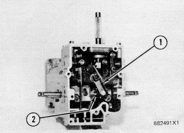
TORQUE RISE COMPONENTS 1. Torque control lever. 2. Cam.
The torque rise control consists of a cam that makes the governor give more fuel to the engine under lug conditions. Different percentages of torque rise can be selected by changing the cam to a programmed rate of rise. This change can be made on or off the engine. Cam selection and high idle settings must be based on factory recommendations. The torque rise control is factory installed. It is not practical to install it in the field. The torque rise cam has three distinct profiles: the base circle area (3); the approach ramp area (4); and the cam lift area (5). The "base circle area" is a radius that does not lift the cam follower. The cam follower must be positioned on the base circle area when the dial indicator is zeroed, for a check or adjustment of the torque rise setting.
The "approach ramp area" is the "transition area" from the base circle to the cam lift area. The "cam lift area" is the area on the cam that lifts the cam follower and torque rise pilot valve lever, which allows additional fuel for torque rise greater than the natural torque rise of the engine.
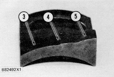
TORQUE RISE CAM 3. Base circle area. 4. Approach ramp area. 5. Cam lift area.
During the torque rise cam adjustment the set point of the terminal shaft is positioned by the synchronizing pin at the full load fuel setting. The cam is moved to position the cam follower on the start of the cam lift area at a specified point that will lift the cam follower 1.00 ± 0.05 mm above the base circle. This removes the free travel (clearances) from the governor and fuel control linkages so the torque rise will occur at the correct engine speed.
Limit/Shutdown Pilot Valve
Shutdown of the engine is done with the limit/ shutdown pilot valve. With the engine running on speed, the ballhead pilot valve is in the centered position. When the limit/shutdown pilot valve is lowered, pressure oil above the control land of the ballhead pilot valve is drained back to the pump area. As engine speed begins to slow, ballhead flyweights move in, lowering the ballhead pilot valve plunger. Oil under the power piston is then drained to the pump area. As the power piston moves down, the output shaft is turned in the decrease direction, and the engine is shut down.
OPERATION OF THE 3161 GOVERNOR
Make reference to the 3161 Governor Schematic for use with the systems operations that follow. The schematic shows the governor pilot valve in the increase fuel position. The 3161 Governor uses engine lubrication oil for its hydraulic system. The oil supply (under pressure) is sent to the governor through an orifice and internal passages. The oil goes from the suction side to the pressure side of the gerotor pump as the drive shaft is turned by the engine. An accumulator spring and piston keeps the pump pressure at approximately 690 kPa (100 psi). The accumulator piston moves up in its cylinder until the pump pressure is 690 kPa (100 psi). At this time, ports in the piston are opened to control the pump pressure. The pump pressure, as set by the accumulator, controls the work output of the governor. Pump pressure is also used for the auxiliary controls installed on the governor top cover.
161 Increase In Speed Setting
When the speed setting shaft is turned clockwise, the speed setting of the governor is increased. The high idle screw limits the high speed setting of the governor. As the speed setting shaft turns, the speed setting lever pushes down on the floating lever which is fastened to the speeder plug. The downward pressure on the speeder plug puts the speeder spring under compression. The speeder spring force then becomes greater than the centrifugal force of the ballhead flyweights, and the ballhead pilot valve plunger is moved down. This increases the governor speed setting.
As the pilot valve plunger is moved down, pressure oil moves under the power piston and pushes the piston up. This moves the terminal lever up and the output shafts are turned in the "increase" fuel direction to increase the engine speed.
Before the engine gets to the new set speed, the compensation system starts to move the pilot valve plunger back to its center position and put the governor under stable control as follows. The oil above the power piston is connected to the upper side of the buffer piston and lower side of the pilot valve compensation land. As the power piston moves up the oil pressure moves the buffer piston down and increases the compression of the lower buffer piston spring. The force of the spring works against the buffer piston movement and this results in a small increase in oil pressure on the upper side of the buffer piston. This higher pressure is directed to the lower side of the pilot valve compensation land and makes a force to push the pilot valve plunger up toward its center position. This stops the flow of pressure oil to the lower side of the power piston and movement of the piston is stopped. As the pilot valve plunger is returned to its center position and the power piston movement is stopped, there is oil leakage through the needle valve orifice. This lets the oil pressure above and below the pilot valve compensation land become equal and the pilot valve plunger movement is stopped and the engine speed is returned to a stable condition. As the pressure above and below the compensation land become equal, the buffer springs return the buffer piston to its center position.


