4 minute read
Air Starting System


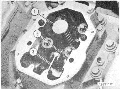
CYLINDER HEAD (Rocker Shaft Removed for Photo Illustration) 1. Injector. 3. Bellcrank. 5. Rack.
FUEL INJECTOR
The injector is held in position by clamp (3). Fuel is injected when rocker arm (2) pushes the top of the injector down. The movement of the rocker arm is controlled by the camshaft through lifter assembly (7) and push rod (4). The amount of fuel injected is controlled by rack (5). Movement of the rack causes rotation of a gear fastened to plunger (6). Rotation of the plunger changes the effective stroke (that part of the stroke during which fuel is actually injected) of the plunger.
Injection timing is a product of two factors; the angular location of camshaft (8) and the location of plunger (6). The angular location of the camshaft is controlled by the camshaft drive gears at the rear of the engine. The location of the plunger can be adjusted with screw (1).
Injection Cycle
When the plunger is at the top of its stroke, fuel flows from the fuel supply chamber, around the injector and through both the lower and upper ports of the barrel. As plunger (6) is moved down by rocker arm (2), fuel is pushed back into the supply chamber through the lower port. The fuel can now go up through a passage in the center of the plunger and out through the upper port of the barrel. As the lower port is closed by the end of plunger (6), fuel can still flow through the upper port until it is closed by the upper scroll on plunger (6). At this point, injection starts and the effective stroke begins. During the effective stroke, fuel is injected into the cylinder until the downward movement of plunger (6) causes the lower scroll to open the lower port and release the fuel pressure. Fuel then goes through the center passage of plunger (6) and the lower port during the remainder of the downstroke. This sudden release of pressure as the lower port is opened causes the fuel to hit the spill deflector with a high force. The spill deflector gives protection to the injector housing (nut) from erosion (wear) because of the force of the released fuel. On the return (UP) stroke, the chamber inside the injector barrel is filled with fuel again.
The plunger can be turned by rack (5) at the same time it is moved up and down by rocker arm (2). The upper section of the plunger has a flat side that fits in the gear, which is engaged with the rack. The plunger slides up and down in the gear, which also has a flat side on its inside diameter. The flat sides let the parts turn together. The rack is engaged with the gear.
When the rack moves, it turns the plunger through the gear. The rotation of plunger (6) controls injection timing and the fuel output of the injector. Rotation of the plunger changes the relation of the plunger scrolls to the ports in the barrel, and this increases or decreases the length of the effective stroke and the point at which injection takes place.
When rack (5) is moved all the way in against the injector body, no injection takes place during the downstroke of the plunger. This is the fuel "SHUT-OFF" position. A small amount of rack movement "OUT" from the injection body is used as a "NO FUEL" movement or "SHUTOFF" position for governing purposes. This "NO FUEL" distance starts at the "ALL-THE-WAY-IN" position of the rack, and ends when the lower scroll opens the lower port and the upper scroll closes the upper port. Movement of the rack "OUT" from this point in the fuel "ON" direction, gives an interval in the plunger stroke when both ports are closed by the plunger and injection takes place. As the rack is moved farther "OUT" in the fuel "ON" direction, the quantity of fuel during the injection stroke increases until a maximum is available at full rack movement.
The scrolls on plunger (6) are used to time the start of injection and set the amount of fuel per injection stroke. The scrolls can change the start of injection in relation to the engine piston position and the length of the effective stroke in relation to the different engine loads. The start of injection can be retarded (made later) with a decrease or increase in injector output according to the engine needs.
During the fuel injection stroke, fuel passes from the barrel chamber through a valve assembly. The valve assembly has a spring-loaded needle valve with a cone shaped end which operates against a seat. The angle of the valve is slightly larger than that of the
FUEL INJECTOR OPERATION 1. Screw. 2. Rocker arm. 3. Clamp. 4. Control rod. 5. Rack. 6. Plunger. 7. Litter assembly. 8. Camshaft.

seat to give line contact. The valve opens at approximately 20 000 to 23 300 kPa (2800 to 3400 psi) and closes at approximately 10 300 kPa ( 1500 psi). The fuel flows from the chamber inside the barrel through drilled passages and grooves in the spring cage, and then through passages around the guide section of the valve to the valve chamber. Here the fuel pressure lifts the needle valve off its seat, and the fuel now flows through the spray tip and out the orifices into the combustion chamber. A flat check valve is used above the needle valve to keep the high pressure combustion gases out of the injector. If the needle valve is held open by small foreign particles for a moment between injection cycles, combustion gases can come into the injector and cause damage. The injector operates with the flat check valve until the foreign particle has washed on through and normal operation takes place.


