2 minute read
Crankshaft Front Seal and Wear Sleeve


HYDRAMECHANICAL SHUTOFF CONTROL
6. Install seat (16), spring (17) and speed sensing valve (9) on the housing assembly guide.
7. Put clean engine oil on O-ring seal (18) and put 0-ring seal (18), plunger assembly (19), spring (20) and seat (21) in position in the housing assembly. Use tool (B) to install snap ring (22) to hold the plunger assembly, the spring and seat in position.
8. If necessary, make a replacement of pin (24) and make sure pin (24) is 3.96 + 0.50 mm (.156 + .020 in.) above the bottom surface of the bore.
9. Install the gerotor assembly as follows: 10.
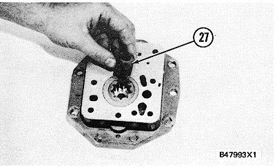
a)Install sleeve (23) and make sure the groove (slot) on sleeve (23) is in alignment with pin (24). b)Put the spring and brush (26) in position in the driven gear (25). Install driven gear (25) in the sleeve. c)Install drive gear (27) in the driven gear.
HYDRAMECHANICAL SHUTOFF CONTROL
10. Install seal (29) on plate (28) and put clean engine oil on it.
11. Install plate (28) on the housing assembly.
12. If necessary, make a replacement of dowels (31) and make sure they are 6.5 + 0.5 mm (.256 + .020 in.) above the surface of the cover assembly.
13. Put gasket (32) in position and install-cover assembly (30) on the plate.
14. Use a press to install shaft (37) in carrier (35) until dimension (X) is 84.08 + 0.25 mm (3.310 + .010 in.).
NOTE: If either or both the shaft and the carrier are new, a hole 3.175 + 0.051 0.000 mm (.125 + .002 .000 in.) in diameter must be drilled through either or both the shaft and the carrier at location (Z) and dimension (Y) must be 5.0 + 0.5 (.197 + .020 in.). This must be done before Step 15 can be done.
15. Install pin (36) to hold the shaft and carrier in position.
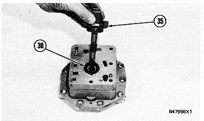
16. Put weights (33) in position on carrier (35) and install dowels (34) to hold the weights. Each weight must move freely on its dowel and must have 0.02 to 0. 18 mm (.001 to .007 in.) end play after assembly. Put marks (counter punch) four places around both ends of the dowels.
17. Install washer (38) on the cover assembly and put carrier assembly (35) in position in the gerotor pump group.