2 minute read
Water Pump


AIR INTAKE SHUTOFF (3508)
REMOVE AIR INTAKE SHUTOFF 1078-11
Advertisement
1. Disconnect the harness assembly to the shutoff solenoid.
2. Remove the bolts to remove shield ( ) and pipes (2) from the engine.
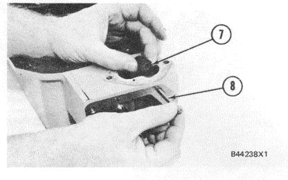
3. Remove the bolts and remove air intake cover (3) from the air shutoff group.
4. Remove bolts (5) and remove air shutoff group (4) from the aftercooler housings.
INSTALL AIR INTAKE SHUTOFF 1078-12
1. Put the gaskets and air shutoff group (1) in position on the aftercooler housings. Install the bolts to hold the group in position.
262
AIR INTAKE SHUTOFF (3508)
2. Put the gasket and air intake cover (2) in position on the air shutoff group. Install the bolts to hold cover (2) in position.
3. Put clean engine oil on the O-ring seals on pipes (4). Put pipes (4) and shield (3) in position on the engine and install the bolts to hold these in position.
DISASSEMBLE AIR INTAKE SHUTOFF 1078-15
start by: a) remove air intake shutoff
1. Remove the bolts from solenoid (1). Hold handle (2) in the position as shown by hand or with a wrench and remove solenoid (1) from the air shutoff group. Slowly release handle (2) to the shutoff position.
2. Bend the locks away from bolts (3) and loosen all of bolts (3) that hold the plate assemblies to the shaft assembly.
263
AIR INTAKE SHUTOFF (3508)
3. Move handle (2) back to the position as shown by hand or with a wrench and put solenoid (1) in position in the shutoff housing assembly. Install the bolts and release the handle.
4. Remove the bolts, the locks, the plates and bushings from plate assemblies (4). Remove plate assemblies (4) from the shaft assembly.
5. Do Step I again to remove solenoid (1).
6. Remove the bolt and remove handle (2) from the shaft assembly.
7. Remove the bolts and remove cover assembly (5) from the housing assembly.
8. Remove seal (6) from cover assembly (5).
9. Remove pin (8) to remove spacer assembly (7) from the housing assembly.
264
AIR INTAKE SHUTOFF (3508)
10. Remove shaft assembly (9), the spacer and spring from the housing assembly. Remove the spring and spacer from the shaft assembly.
11. If necessary, remove the dowel and remove lever (10), spacer assembly (12) and pin ( 11 ) as a unit from shaft assembly (9). Remove pin (11 ) from lever (10) to remove spacer assembly (12) from lever (10) if necessary.
ASSEMBLE AIR INTAKE SHUTOFF 1078-16
Tools Needed A 1P510 Driver Group 1
1. If necessary, make a replacement of dowel (1) and make sure the end of the dowel as shown is 83.0 ± 0.5 mm (3.268 ± .020 in.) below surface (X).
2. If shaft assembly (2) was disassembled, put spacer assembly (5) in position on lever (3) and use a press to install pin (4) until it is even (flush) with the surface of lever (3) as shown. Put lever (3), spacer assembly (5) and pin (4) as a unit in position on shaft assembly (2). Install the dowel to hold the unit on shaft assembly (2) and put marks (stake) the end of the dowel.


