
5 minute read
Hydraulic Circuits (Later


Air Inlet Shutoff
The air inlet shutoff consists of a shutoff valve in the engine air inlet housing and a hydraulic actuator that holds the shutoff valve in the "OPEN" position.
If an engine is operated in a combustible atmosphere, such as an oil or gas blow out on an oil rig, the air supply must be stopped to give a positive method of engine shutdown. If only the fuel control linkage was moved to the "SHUTOFF" position, the engine may continue to run on the air-oil-gas mixture pulled into the engine air intake.
The hydramechanical protective system closes the air inlet shutoff valve to stop combustion air supply to the engine in an overspeed condition, to give a more positive shutdown. The air inlet shutoff valve is also closed when the emergency manual shutoff is operated.
Since overspeed is a serious occurrence, the air inlet shutoff must be manually reset. This action requires a person t6 physically go to the engine and see if any damage has occurred.
Fuel Shutoff Actuator
This actuator is located on top of the Woodward UG-8 or the Caterpillar 3161 Governor. The actuator can be either an electric or hydraulic actuator that is operated any time the hydramechanical protective system causes engine shutdown. When operated by the diverter valve, the actuator moves the governor shutoff strap which causes the governor to move the engine fuel control linkage to the "SHUTOFF" position.
COMPONENT LOCATIONS ON ENGINE
SHUTOFF CONTROL GROUP 1. Oil lines to air inlet shutoff actuator. 2. Rack sequence valve. 3. Shutoff control group. 4. Engine oil pressure line. 5. Emergency manual shutoff valve. 6. Cover (oil reservoir). 7. Diverter valve. 8. Air inlet sequence valve. SHUTOFF CONTROL GROUP 3. Shutoff control group. 4. Engine oil pressure line. 7. Diverter valve. 9. Oil line to thermostatic pilot valve. 10. Oil line to fuel shutoff actuator.


AIR INLET SHUTOFF 11. Air inlet shutoff housing. 12. Air inlet shutoff actuator. 13. Aftercooler housing.
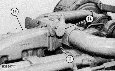
AIR INLET SHUTOFF 11. Air inlet shutoff housing. 13. Aftercooler housing. 14. Reset knob.
213
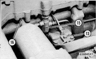
COOLANT TEMPERATURE PROTECTION 13. Aftercooler housing (coolant inlet). 15. Thermostatic pilot valve. 16. Housing (below regulator housing).

GOVERNOR SHUTOFF ACTUATOR (Woodward UG-8 Governor Shown) 9. Oil line to thermostatic pilot valve. 10. Oil line to fuel shutoff actuator. 17. Fuel shutoff actuator. SYSTEM HYDRAULICS
Engine lubrication oil (under pressure) is sent to the oil reservoir for the shutoff control. The reservoir keeps the correct level of oil for the system and drains the excess oil back into the engine. This gives a constant oil supply to the system.
An oil pump and pressure relief valve (located in the shutoff control group) supplies oil flow and pressure for the protective system hydraulic circuits.
There are two main hydraulic circuits in the protective system. One circuit is for the fuel shutoff and the other is for air inlet shutoff. A constant flow of oil through the air inlet shutoff circuit removes (bleeds) air and keeps the lines full of oil to give a minimum time for system response. If a fault condition occurs, the oil pressure in one or both hydraulic circuits is increased to operate an actuator to shutdown an engine or activate an alarm.
HYDRAULIC CIRCUITS (EARLIER)
(Without Check Valves In Diverter Valve)
The schematics that follow, show only hydraulic actuators that are filled to cause engine shutdown. The fuel shutoff actuator can be replaced with an electric solenoid that is operated by the system hydraulics with the use of a pressure switch.
NOTE: Some of the schematics show only the components needed for explanation and do not show the complete hydramechanical protective system circuits.
214
SCHEMATIC NO. 1 (COMPLETE HYDRAMECHANICAL PROTECTIVE SYSTEM) 1. Selector valve. 2. Low speed oil protection valve. 3. Start-up override valve. 4. Diverter valve orifice. 5. Engine oil pressure orifice. 6. Speed sensing valve spool. 7. Diverter valve. 8. Fuel shutoff actuator. 9. Thermostatic pilot valve. 10. High speed oil protection valve. 11. Emergency manual shutoff valve. 12. Air inlet shutoff actuator. 13. Air inlet sequence valve. 14. Pilot operated two-way valve. 15. Fuel shutoff sequence
valve. 16. Air inlet shutoff valve. 17. Oil pump. 18. Oil pressure relief valve.
215

SCHEMATIC NO. 2 (LOW ENGINE OIL PRESSURE CIRCUIT) (Low Speed Range) 1. Selector valve. 2. Low speed oil protection valve. 4. Diverter valve orifice. 6. Speed sensing valve spool. 7. Diverter valve. 8. Fuel shutoff actuator. 10. High speed oil protection valve. 15. Fuel shutoff sequence valve. 17. Oil pump.
LOW SPEED RANGE (NORMAL ENGINE OIL PRESSURE)
Make Reference to Schematic No. 2

When an engine is started and speed increases, engine oil pressure moves low speed oil protection valve (2) open. At the same time, oil in the protective system flows from oil pump (17) to fuel shutoff sequence valve ( 15) and diverter valve (7). Fuel shut- off sequence valve (15) keeps the inlet pressure to diverter valve (7) at 760 kPa (110 psi) and then directs the remainder of oil flow through the air inlet shutoff circuit. Most of the air inlet shutoff circuit has been left out since it is not directly in use at this point. At diverter valve (7), the oil flows through orifice (4) which causes a pressure difference across both ends of the valve spool. The valve spool is then moved by system oil pressure, against a spring force, to keep the fuel shutoff actuator from being operated. The oil then flows from diverter valve (7) to drain through low speed oil protection valve (2) and selector valve ( I ).
NOTE: Engine oil pressure is not high enough at this point to move valve (10) against the force of the spring.


