
1 minute read
Electrical Switches


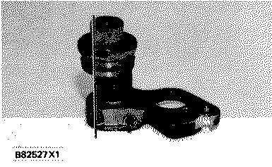
SPEED SETTING BELLOWS AND LEVER
There is an index mark (notch) 0.76 mm (.030 in.) deep on the outer face of the bellows flange. The index mark is approximately mid range position when it is turned to the front of the governor (when facing the governor name plate).

SPEED SETTING CONTROL 1. Air inlet port. 2. Feedback spring. 3. Pivot.
Control air pressure enters the bellows through air inlet port (1) at the top of the flange. Control air pressure expands the speed setting bellows, which pushes down on the lever at the left of pivot (3), raising the right end of the lever against feedback spring (2). The force of the feedback spring is marked on the end of the spring.
When the bellows is turned, the eccentric changes the position of the bellows on the speed setting lever. This changes the length of the lever arm. The lever arm is the distance from pivot (3) to the outer edge of the bellows.
When the bellows is turned with the index mark to the right side of the governor (counterclockwise as seen from governor nameplate), the bellows moves closer to the pivot pin. This makes the lever arm shorter and lowers engine speed for a given amount of air pressure.
194 LOWER SPEED SETTING

HIGHER SPEED SETTING
With the index mark to the left side of the governor (as seen from governor nameplate), the bellows is farther away from the pivot pin. The lever arm is now longer and engine speed is increased for a given amount of air pressure.
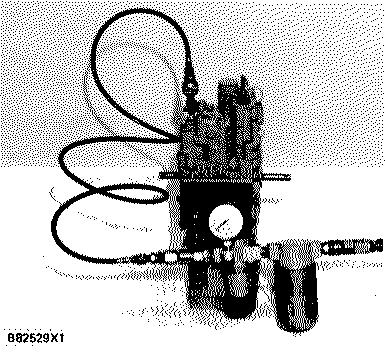
CONNECT PRESSURE REGULATOR AND GAUGE ASSEMBLY
Before the control adjustment can be made, install n pressure regulator and gauge assembly in the control air supply line. Also, connect a tachometer with good accuracy to the engine.


