3 minute read
Valve Clearance


1. Remove all valve covers on the same side of the engine that camshaft needs adjustment. Now loosen bolts (1) [that hold all rocker shafts (2) to valve cover bases] until all rocker arms are free from the injectors and the valves.
NOTE: The above procedure must be done before camshaft drive gear (7) is pulled off the camshaft taper.
Advertisement
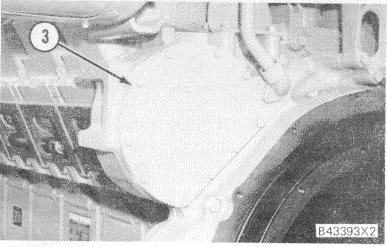
REMOVE COVER (LH SIDE) 3. Cover.
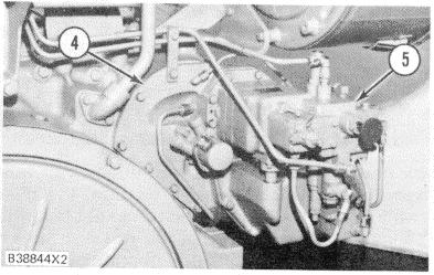
2. Remove camshaft drive gear cover (3) from the left side of the flywheel housing. Remove hydramechanical shutoff control group (5) and the shutoff drive (4) from the right side of the flywheel housing.
NOTE: See DISASSEMBLY AND ASSEMBLY install the hydramechanical protective system.
REMOVE HYDRAMECHANICAL PROTECTIVE SYSTEM (RH SIDE) 4. Hydramechanical shutoff drive. 5. Hydramechanical shutoff control group.
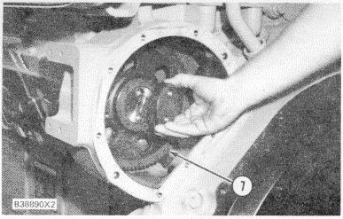
3. Remove bolts (6) and gear (8) from the right camshaft drive gear (7). Remove the bolts and plate from the left camshaft drive gear.
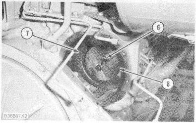
REMOVE CAMSHAFT DRIVE GEARS (RH SIDE) 6. Bolt. 7. Drive gear. 8. Accessory drive gear for hydramechanical protective system.
4. Install the 6V3010 Puller Group, two 9S9089 Bolts and two 5P1076 Washers. Loosen drive gears (7) from the taper on the camshafts. Remove the tooling and the gears.
5. Remove timing pin(s) (10) from the storage position (under the rear camshaft covers) on each side of the engine.
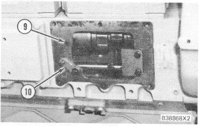
CAMSHAFT TIMING 9. Timing hole. 10, Timing pin.
6. Turn the camshafts until timing pins (10) can be installed through timing holes (9) and into the grooves (slots) in the camshafts.
119
INSTALL CAMSHAFT DRIVE GEARS 7. Drive Gear.
7. Install camshaft drive gears (7) as follows:
a. Put camshaft drive gears (7) in position on the camshafts.
b. Use hand pressure to turn and hold camshaft drive gears (7) in the direction of normal engine rotation. This removes all gear clearance (backlash) between camshaft drive gears (7) and the idler gear.
c. Install the plate (on left side of engine) and drive gear (8) for the hydramechanical protective system (on right side of engine) to hold camshaft drive gears (7) to the camshaft.
d. Tighten the bolts in steps to a torque of 100 ± 15 N m (75 ± 11 lb. ft.).
e. Hit the face of the plate and drive gear and tighten the bolts to a torque of 100 ± 15
N m (75 ± 11 lb. ft.).
f. Again hit the face of the plate and drive gear and again tighten the bolts to a torque of 100 ± 15 N m (75 ± 11 lb. ft.).
NOTE: If necessary, do Step 7f until the bolts hold torque (can not be moved) to make sure the drive gears are in full contact with the taper on the camshafts.
8. Install the gasket and cover on the left side of the flywheel housing.
9. Install the hydramechanical protective system on the right side of the flywheel housing.
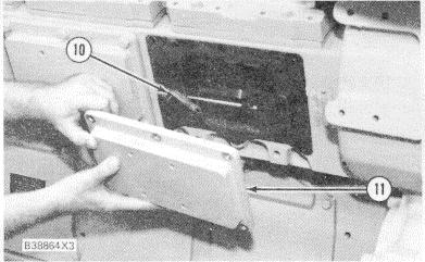
10. Remove timing pins (10) from the camshafts. Remove the timing bolt from the flywheel housing. Install timing pins (10) in their storage positions. Install covers (11) over the camshafts and timing pins.
120
STORAGE POSITION FOR TIMING PINS 10. Timing pin. 11. Cover.
11. Install the 5M6213 Plug in the flywheel housing timing hole. Remove the engine turning pinion and install the cover and gasket.
12. Make sure the rocker arms are engaged correctly with the push rods and tighten the bolts to hold all of the rocker shafts in position.
13. Make adjustments to the valves and injector timing. See VALVE CLEARANCE SETTING and FUEL TIMING for the correct procedures.
START UP PROCEDURE
Use this procedure when an engine is started for the first time after work is done on the fuel system or governor.
1. Disconnect the air inlet system from the turbochargers.
2. Have a person in position near each turbocharger air inlet with a piece of steel plate large enough to completely cover the turbocharger air inlet.
Be careful when plate is put against air inlet opening. Due to excessive suction, the plate can be pulled quickly against air inlet openings. To avoid crushed fingers, do not put fingers between plate and air inlet opening.
3. Start the engine. If the engine starts to run too fast or runs out of control, immediately put the steel plates against the turbocharger air inlets. This will stop the air supply to the engine, and the engine will stop.


