2 minute read
Lower Front Gear Group


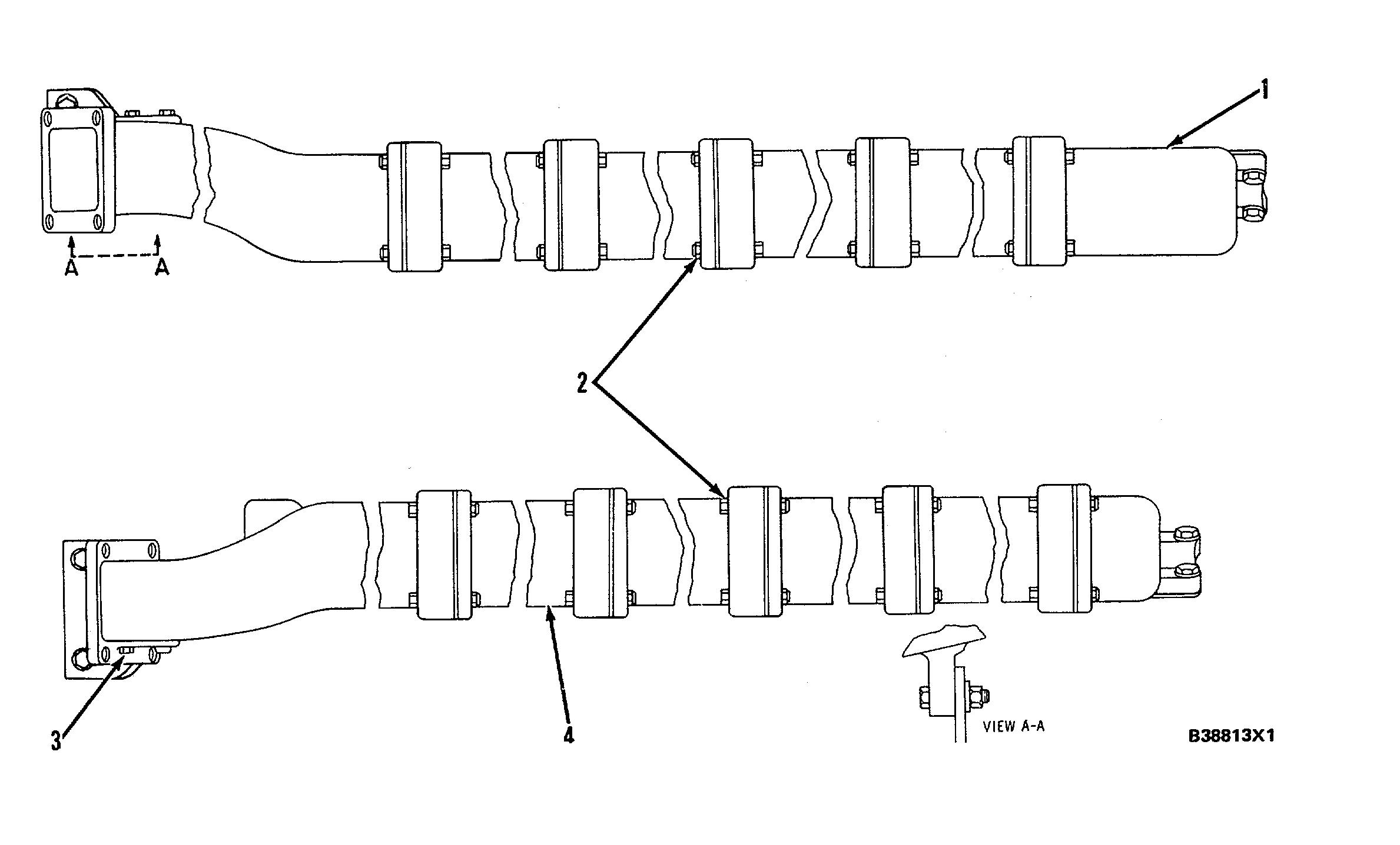
EXHAUST MANIFOLDS
(3512 EXHAUST MANIFOLDS ILLUSTRATED)
(1) Left exhaust manifolds.
(2) Put 5P3931 Anti-Seize Compound on the threads of all exhaust manifold bolts, nuts and plugs (3).
Torque for all exhaust manifold bolts and nuts........... 45 ±7 N-m (32 ±5 lb. ft.)
(3) 5B7890 Plugs.
Torque for exhaust manifold plugs......................... 35 N•m (25 lb. ft.)
(4) Right exhaust manifolds
22
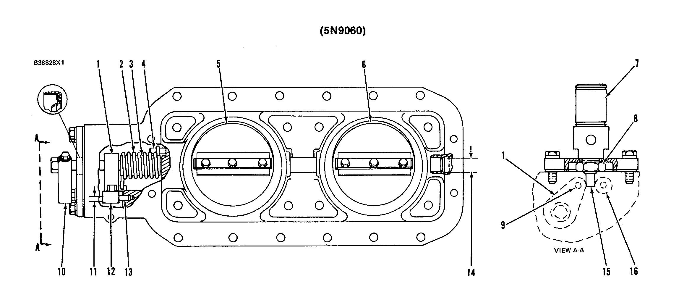
(1) Install shaft assembly in housing as follows
a. Install spacer (3) and spring (2) on shaft assembly (1). b. Install the assembly in the housing Turn spring (2) until It engages correctly with pin (4)
c Install handle (10) on the shaft assembly (1) Turn shaft assembly (1) upward and install pin (13) so handle (10) can rest on pin (13).
d. With the shaft assembly and handle (10) In contact with pin (13), Install plate assemblies (5) and (6) on the shaft assembly. e. Remove pin (13) to release the handle and let plate assemblies (5) and (6) move to the "shutoff" position. A 0.076 mm (.003 in) feeler gauge should not pass between each plate assembly and the housing.
f. Remove handle (10) and Install spacer assembly (12), pin, (13), the gasket, cover assembly and handle (10). (2) Spring (3) Spacer for spring (2).
Bore In spacer for shaft..20 80 ±0 25 mm (819 +.010 in) Diameter of shaft.............. 18.94 ±0.02 mm (.746 + .001 In )
(4) Pin
(5) Plate assembly
(6) Plate assembly (7) Hydraulic cylinder must be Installed before the air shutoff can be installed on the engine. Put the air shutoff group in the "open" position and install the gasket, flange and cylinder with cylinder shaft (15) between the spacer assembly in the shaft lever and spacer assembly (16). The bolts that hold the unit to the aftercooler housing can now be installed. (8) Torque for nut that holds cylinder to flange........45 ±7 N•m (33 ± 5 lb ft
(9) Diameter of pin6.299 ±0.008 mm (2480 ±.0003 In )
Bore in spacer bushing for pin (after assembly)................... 6.314 ±0.011 mm ( 2486 ±.0004 n )
Bore in spacer for bushing.........7.938 ±0.013 mm (.3125 +.0005 In.)
(10) Handle
(11) Diameter of pin (13).......................6.299 ±.0.008 mm (2480 ±.0003 in )
Bore in housing for pin ..............................6.408 ±0.051 mm (.2523 ±.0020 in)
Bore in spacer bushing for pin (after assembly)................... 6.314 ±0.011 mm (.2486 ±.0004 in.)
Bore in spacer for bushing ........7.938 ± 0.013 mm (.3125±.0005 in) (12) Spacer.
(13) Pin.
(14) Diameter of shaft ......................18.94 ±0.02 mm (.746 ±.001 In) Inside diameter of bushings for shaft ......................19.050 ±0.044 mm (.7500 ±.0017 In) (15) Hydraulic cylinder shaft
(16) Spacer assembly


