12 minute read
Hydramechanical Shutoff Control


TURBOCHARGERS (3508)
10. Install seal rings (10) on spacer ( 11 ) so the gaps in the rings are 180° apart.
11. Install spacer ( 11) in backplate assembly (12) with the chamfer end of the spacer toward the cartridge housing.
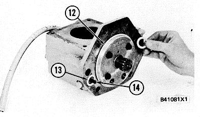
12. Make sure the oil passage in the cartridge housing and the backplate assembly are in alignment. Put the backplate assembly (12) in position on the cartridge housing.
13. Install the locks and bolts to hold backplate assembly (12) to the cartridge housing. Tighten the bolts to a torque of 10 + 1.1 N•m (90 + 10 lb. in.) and bend the tabs of the locks on the bolts.
14. Install tool (C) in tool (B). Put the turbine shaft in position in tooling (C). Put 6V2055 High Vacuum Grease in the groove for seal ring ( 14). Make sure the grease fills the groove approximately one half or more of the groove depth for the complete circumference of the groove to help make a carbon dam under the seal ring. Install seal ring (14) and shroud (15) on turbine shaft (13).
15. Install the cartridge housing on the turbine shaft while spacer (11) is held in position. Make sure the seal ring on the turbine is fitted correctly in the cartridge housing.
16. Put compressor wheel (16) in position on the turbine shaft.
319
TURBOCHARGERS (3508)
NOTICE Do not put a side force on the turbine shaft when the nut is tightened or a bent shaft will be the result.
17. Put a small amount of oil on the turbine shaft threads and the compressor wheel face that will be under the nut. Install the nut and tighten it to a torque of 13.6 N•m (120 lb. in.) to push the compressor wheel (16) on the shaft. Loosen the nut and tighten it again to 3.4 N•m (30 Ib. in.). Tighten the nut 1200 of a turn more.
18. Put the cartridge housing in a vise as shown. Check the shaft end play with tool group (D). The shaft end play must be 0.08 mm to 0.25 mm (.003 to .010 in.).
19. Install turbine housing (17) on tool group (E) as shown. Put the cartridge and clamp (18) in position in turbine housing (17). Make sure the marks on the housing and cartridge are in alignment and tighten clamp (18) to a torque of 13.6 + 1.1 N•m (120 + 10 lb. in.). Lightly hit all around the clamp with a soft faced hammer and again tighten clamp nut to same torque.
20. Install clamp and compressor housing (19) on the cartridge in the correct position. Move clamp into position and tighten the nut to a torque of 13.6 + 1.1 N•m (120 + 10 lb. in.). Lightly hit all around the clamp with a soft faced hammer and again tighten clamp nut to the same torque.
end by:
a)install turbochargers
320
EXHAUST MANIFOLDS
REMOVE EXHAUST MANIFOLDS 1059-11
start by: a) remove turbochargers b) remove air intake shutoff (3508)
1. Remove bracket (1) that holds the rear of the exhaust manifold in position.
2. Fasten a hoist to exhaust manifold (2) and remove the bolts that hold it to each cylinder head. Remove the exhaust manifold from the engine. The weight of the 3512 exhaust manifold is 56 kg (125 lb.). The weight of the 3508 exhaust manifold is 49 kg (110 lb.).
INSTALL EXHAUST MANIFOLDS 1059-12
1. If the exhaust manifold was disassembled, put 5P3931 Anti-Seize Compound on the threads of the bolts and nuts at assembly.
2. Fasten a hoist and put exhaust manifold (1) and the gaskets in position on the engine.
NOTE: The gaskets can be fastened to the exhaust manifold ports with tag wire or short 3/8"-16 NC studs can be used as guide bolts for alignment at assembly.
3. Put 5P3931 Anti-Seize Compound on the threads of the bolts and install them to hold the exhaust manifolds to the cylinder heads. Tighten the bolts to a torque of 45 + 7 N-m (32 + 5 lb. ft.).
4. Install bracket (2) to hold the rear of the exhaust manifold in position. start by:
a) install turbochargers b) install air intake shutoff (3508)
321
AFTERCOOLER
REMOVE AFTERCOOLER 1063-11
Tools Needed A
6V2156 Link Bracket 2
start by: a) remove air intake shutoff
1. Drain the coolant from the cooling system.
2. Remove the two bolts to remove elbow (1) and a sleeve from the rear of the aftercooler housings.
3. Remove adapter (2) from the rear of aftercooler housings.
4. Disconnect tube assembly (3) from adapter (5) and the water temperature regulator housing. Remove the tube assembly from the engine.
5. Remove all the bolts that hold elbow (4) in position and disconnect elbow (4) from adapter (5).
6. Remove the two bolts and remove adapter (5) from the front of the aftercooler housings.
AFTERCOOLER
7. Remove sleeve (7) from adapter (6) and remove adapter (6) from the front of the aftercooler housings.
8. Fasten a hoist to aftercooler housings (8) with tooling (A). Remove the bolts to remove aftercooler housings (8) from the engine. The weight of the 3508 Aftercooler Housings is 28 kg (62 lb.) and the 3512 Aftercooler Housings is 66 kg (145 lb.).
NOTICE Be careful when the aftercooler core is removed because the lower rear part of the core is held in position by a connector and O-ring seals.
9. Fasten a hoist to strap (11) and remove the bolts and two plates that hold aftercooler core (10) in position. Remove aftercooler core (10) from the engine. The weight of the 3512 Aftercooler Core is 39 kg (85 lb.). The weight of the 3508 Aftercooler Core is 29 kg (65 lb.).
NOTE: The 3512 and 3508 Engines use the same aftercooler core but the 3508 Engines do not have pipes (9) at the ends of the core or the two plates to hold the core in position.
10. Remove pipes (9) from the ends of the aftercooler core and remove the O-ring seals from the tubes.
11. Remove O-ring seals (12) from each end of the aftercooler core. Remove ring (13) to remove connector (14) from the aftercooler core. Remove the O-ring seals from the connector.
AFTERCOOLER
INSTALL AFTERCOOLER 1063-12 Tools Needed A
6V2156 Link Bracket 2
NOTE: Clean and inspect all of the O-ring seals and gaskets. Make a replacement of any worn or damaged seals and gaskets.
1. Install the O-ring seals on connector (1) and put clean engine oil on the seals. Put connector (I) in position and install ring (2) to hold the connector in position.
2. Install the O-ring seals on the ends of the aftercooler core and put clean engine oil on the seals.
3. Install the O-ring seals on pipes (3) and put clean engine oil on the seals. Install pipes (3) on the ends of the 3512 Aftercooler Core only.
4. Fasten a hoist to aftercooler core (4) as shown and put it in position on the engine. Make sure connector (I) is correctly engaged with adapter (5) in the cylinder block. Install the bolts and plates to hold the core in position. The 3508 Engines do not use the plates.
5. If the aftercooler housings were taken apart and new gaskets installed, cut the gaskets even with the bottom of the housings.
6. Fasten a hoist to aftercooler housings (6) with tooling (A). Put housings (6) and the gasket in position and install the bolts to hold the housings in position. Tighten the bolts to a torque of 55 + 7 N•m (40 + 5 lb. ft.).
7. Put clean engine oil on the O-ring seal on adjuster (7). Install adapter (7) and sleeve (8) in the front of the aftercooler housings and over the end of the pipe.
324
AFTERCOOLER
8. Put clean water on the O-ring seal and put adapter (10) and the gasket in position in the front of the aftercooler housings. Install the bolts to the adapter.
9. Put clean water on the O-ring seal and push elbow (9) into adapter (10). Put the gasket in position between elbow (9) and the tube. Install the bolts to hold elbow (9) in position.
10. Install tube assembly (11) on the regulator housing and adapter (10).
11. Put clean engine oil on the O-ring seal and install adapter (12) in the rear of the aftercooler housings and over the end of the pipe.
12. Put clean water on the O-ring seal on elbow (14). Install sleeve (13) and elbow (14) in the rear of the aftercooler housings. Make sure sleeve ( 13) is over the end of the pipe and install the bolts to hold elbow (14).
end by: a) install air intake shutoff
325
GOVERNOR
REMOVE GOVERNOR 1264-11
1. Drain the coolant from the cooling system.
2. Remove the bolts and retainers to remove tube (1) from the engine.
3. Disconnect hose assemblies (3) and (4) from the governor. Disconnect hose assembly (2) from the engine and remove it from the governor.
4. Remove bolts (5) that hold the governor fastener group to the engine.
5. Remove bolts (7) to remove governor (6) and the fastener group as a unit from the engine. The weight of the unit is 23 kg (50 lb.).
6. Remove the bolt and remove lever assembly (10) from the governor output shaft. If necessary, remove pin (11) from the lever assembly.
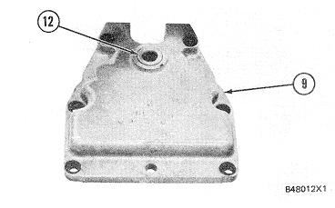
7. Remove bolts (8) and remove cover (9) from the governor.
8. Remove seal (12) and the washer from cover (9).
326
GOVERNOR
INSTALL GOVERNOR1264-12
Tools Needed A
1P510 Driver Group 1
1. Install the washer in cover (1) and use tool group (A) to install the seal in cover (1). Make sure the lip of the seal is toward the engine as shown and put clean engine oil on the seal.
2. Make sure two bolts (3) are in position and put cover (1) in position on the governor. Install.48013X1 bolts (2) to hold the cover in position.
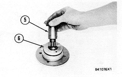
3. If pin (5) was removed, use a press to install the new pin until it is 18 ± 1 mm (.71 ± .04 in.) above the surface of the lever assembly as shown. Put lever assembly (4) in position on the governor output shaft and install the bolt to hold it.
4. Put the gaskets for the governor and the fastener group in position on the engine. Fasten a hoist or use two men to put governor (6) and the fastener group as a unit in position on the engine. Make sure the pin on lever assembly (4) engages in the groove (slot) of the lever for the fuel control. Make sure the splines on the governor input shaft are engaged correctly in the governor drive and install the bolts to hold the governor and fastener group in position.
5. Install hose assembly (7) on the governor and connect it to the engine. Connect hose assemblies (8) and (9) to the governor.
6. Put clean engine oil on the O-ring seals and’ install tube (10) on the engine. Install the bolts and retainers to hold the tube in place.
7. Fill the cooling system with coolant to the correct level.

GOVERNOR DRIVE
REMOVE AND INSTALL GOVERNOR DRIVE 1288-10
start by: a) remove governor
1. Remove bolts (2) and pull governor drive (1) from the front drive housing.
2. Make sure the O-ring seals are in position on the front of governor drive (1) and put clean engine oil on the seals.
3. Put governor drive (1) in position and install bolts (2) to hold it to the front drive housing. end by: a) install governor401X
DISASSEMBLE GOVERNOR DRIVE 1288-15
start by: a) remove governor drive
1. Remove O-ring seals (1), (2) and (3) from the front of the governor drive housing.
2. Remove the bolts that hold adapter (4) in position and pull adapter (4) from the housing.
3. Remove pinion (5), shims (6), seals (7) and (8) from adapter (4). Make a measurement of the.4-0 thickness of shims (6) and put identification on them for assembly purposes.
328
GOVERNOR DRIVE
4. Remove hose assembly (9), cover (11) and the gasket from governor drive housing (10).
5. Remove gear (13) and coupling (12) from housing (10) as a unit.
6. Remove ring (14) to remove coupling (12) from gear (13).
7. If necessary, remove bearing (1 5 ) from housing (10).
329
GOVERNOR DRIVE
ASSEMBLE GOVERNOR DRIVE 1288-16
Tools Needed A B
1P510 Driver Group 1 8S2328 Dial Test Indicator Group 1
1. Make an alignment of the oil hole in the bearing with the drilled oil passage in governor drive housing (1). Use tool group (A) and install the bearing in housing (1) until it is 1.0 ± 0.5 mm (.039 ± .020 in.) below the inside surface of the housing.
2. Put coupling (3) in position in gear (2) and install ring (4) to hold the gear and coupling as a unit.
3. Install coupling (3) and gear (2) as a unit in housing (1).
4. Install pinion (5) in adapter (6).
330
GOVERNOR DRIVE
5. Put adapter (6) and shims (7) of the original thickness in position and install the bolts to hold the unit together.
6. Make an adjustment of the gear clearance (backlash) between gear (2) and the pinion as follows:
a) Install tool group (B) on gear (2) as shown to check the gear clearance (backlash) at four locations around gear (2) 90° apart.
b) Hold the pinion in position and push down" while gear (2) is moved back and forth.
Make a record of the indications on tool group (B) and use the lowest indication as the correct gear clearance (backlash) value. The correct gear clearance (backlash) is 0.100 + 0.050 or 0.025 mm (.0039 + .0020 or .0010 in.).
c) Add or subtract shims (7) as necessary until the gear clearance (backlash) is correct.
7 Remove tool group (B), the adapter and pinion from the housing.
8. Connect hose assembly (8) to housing (1). Put the gasket and cover (9) in position and install the bolts and washers to hold them to housing (1).
9. Install seals (10) and (11) on adapter (6) and put clean engine oil on them.
10. Install the correct amount of shims (7) and adapter (6) with the pinion in housing (1) and tighten the bolts.
11. If necessary, make a replacement of pins (14).( Make sure the pins are 14 ±1 mm (.55 ±.04 in.) above the surface of the housing.
12. Install O-ring seal (12) and seals (13) on the front of the housing. Put clean engine oil on the seals. end by: a) install governor