1 minute read
Crankshaft Vibration Damper


HYDRAMECHANICAL SHUTOFF CONTROL
ASSEMBLE HYDRAMECHANICAL SHUTOFF CONTROL
Tools Needed A B C
1P510 Driver Group 1 1P1853 Pliers 1 1 1P1855 Pliers 1
1. If necessary, make a replacement of dowels (2) and make sure they are 3.0 + 0.5 mm (.118. + .020 in.) above the surface of the housing assembly.
2. Put guide (I) in position in the housing assembly and make sure the dash mark on the end of, the guide is in alignment with hole (3). Use tool group (A) to install guide (I) in the housing assembly.
3. Put lever (5) in position in the housing assembly as shown and install shaft (4) to hold lever (5) in position. Make sure the end of the shaft is, a even (flush) + 0.25 (.010 in.) with the housing assembly.
4. Put the seat, spring (7) and seat (6) in position in cover (8) and put cover (8) and the gasket in position on the housing assembly. Install the bolts to hold the cover in position.
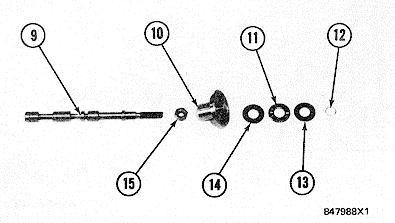
5. Install nut (15) and seat (10) on speed sensing valve (9). Make sure the dimension between the end of the valve and the nut face of the seat is 117.21 + 0.25 mm (4.614 + .010 in.) and tighten the nut. Put race (14), bearing (11) and race (13) in position on seat (10) and install ring (12) to hold these in position.


