6 minute read
Operation of the 3161 Governor


3. Look at the gauge for the exact pressure that makes the pressure cap open.
4. Make a comparison of the reading on the gauge with the correct pressure at which the pressure cap must open.
NOTE: The correct pressure that makes the pressure cap open is on the pressure cap and is also in the SPECIFICATIONS.
5. If the pressure cap is bad, install a new pressure cap.
Radiator and Cooling System Leak Tests (Systems That Use Pressure Cap)
Tools Needed: 9S8140 Cooling System Pressurizing Pump Group.
To test the radiator and cooling system for leaks, use the procedure that follows:
DO NOT loosen the filler cap or pressure cap on a hot engine. Steam or hot coolant can cause severe burns.
1. After the engine is cool, loosen the pressure cap to the first stop and let the pressure out of the cooling system. Then remove the pressure cap.
2. Make sure the coolant is over the top of the radiator core.
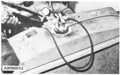
3. Put the 9S8140 Cooling System Pressurizing Pump Group on the radiator.
9S8140 PRESSURIZING PUMP GROUP INSTALLED ON RADIATOR THAT USES PRESSURE CAP (TYPICAL EXAMPLE)
4. Get the pressure reading on the gauge to 20 kPa (3 psi) more than the pressure on the pressure cap.
5. Check the radiator for outside leakage.
6. Check all connections and hoses of the cooling system for outside leakage.
7. If you do not see any outside leakage and the pressure reading on the gauge is still the same after 5 minutes, the radiator and cooling system does not have leakage. If the reading on the gauge goes down and you do not see any outside leakage, there is leakage on the inside of the cooling system. Make repairs as necessary.
Water Temperature Gauge Test
Tools Needed: 8T470 Thermistor Thermometer Group or 2F7112 Thermometer and 6B5072 Bushing
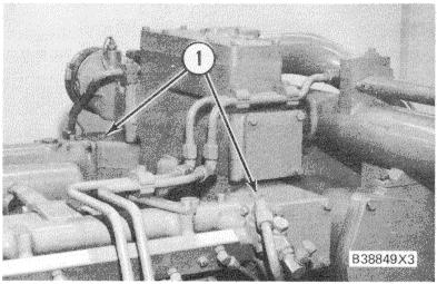
TEST LOCATION 1. Plug (one on each side of engine).
Check the accuracy of the water temperature gauge if either of the conditions that follow are found: 1. The gauge reads normal, but the engine is too hot and a loss of coolant is found.
2. The gauge shows that the engine is hot, but no loss of coolant can be found.
Remove plug (1) [1/2 Std. Pipe Thread] and install the 8T470 Thermistor Thermometer Group or the 2F7112 Thermometer and 6B5072 Bushing. A temperature gauge of known accuracy can also be used to make this check.
Work carefully around an engine that is running. Engine parts that are hot, or parts that are moving, can cause personal injury.
Start the engine and run it until the temperature reaches the desired range according to the test thermometer. If necessary, put a cover over part of the radiator or cause a restriction of the coolant flow. The reading on the gauge for water temperature should agree with test thermometer within the tolerance range of the gauge. Make reference to SPECIFICATIONS or ATTACHMENT SPECIFICATIONS in this manual to find correct range for a specific gauge.
Water Temperature Regulator Test.
1. Remove the regulator from the engine. 2. Heat water in a pan until the temperature is 920C (1970F). Move the water around in the pan to make it all the same temperature.
3. Hang the regulator in the pan of water. The regulator must be below the surface of the water and it must be away from the sides and bottom of the pan.
4. Keep the water at the correct temperature for 10 minutes.
5. After ten minutes, remove the regulator and immediately measure the distance the regulator has opened. The distance must be a minimum of 9.53 mm (.375 in.).
6. If the distance is less than 9.53 mm (.375 in.), make a replacement of the regulator.
V-BELT TENSION CHART
BELT SIZE
WIDTH BELT TOP WIDTH TOP OF PULLEY GROOVE BELT TENSION “INITIAL” GAUGE READING BELT TENSION “USED”** GAUGE READING
BORROUGHS GAUGE NUMBERS mm in. mm in. N lb. N lb. OLD GAUGE NO. NEW GAUGE NO.
3/8 10.72 .422 9.65 .380 445 + 22 100 + 5 400 + 22 90 + 5 BT-33-73F BT-33-95 1/2 13.89 .547 12.70 .500 534 + 22 120 + 5 400 + 44 90 + 10 BT-33-96-4-16 BT-33-95 5V 15.88 .625 15.24 .600 534 + 22 120 + 5 400 + 44 90 + 10 BT-33-72-4-15 BT-33-72C 11/16 17.48 .688 15.88 .625 534 + 22 120 + 5 400 + 44 90 + 10 BT-33-72-4-15 BT-33-72C 3/4 19.05 .750 17.53 .690 534 + 22 120 + 5 400 + 44 90 ± 10 BT-33-72-4-15 BT-33-72C 15/16 23.83 .938 22.30 .878 534 + 22 120 + 5 400 + 44 90 + 10 BT-33-72-4-15 BT-33-72C MEASURE TENSION OF BELT FARTHEST FROM THE ENGINE *"INITIAL" BELT TENSION is for a new belt. **"USED" BELT TENSION is for a belt which has more than 30 minutes of operation at rated speed of engine. A10232-1X1
144
BASIC BLOCK
CONNECTING ROD BEARINGS
The connecting rod bearings fit tightly in the bore in the rod. If bearing joints or backs are worn (fretted), check bore size. This can be an indication of wear because of a loose fit.
Connecting rod bearings are available with 0.63 mm (.025 in.) and 1.27 mm (.050 in.) smaller inside diameter than the original size bearings. These bearings are for crankshafts that have been ground (made smaller than original size).
MAIN BEARINGS
Main bearings are available with a larger outside diameter than the original size bearings. These bearings are for cylinder blocks that have had the bore for the main bearings "bored" (made larger than the original size). The size available is 0.63 mm (.025 in.) larger outside diameter than the original size bearings.
CYLINDER BLOCK
The bore in the block for main bearings can be checked with the main bearing caps installed without bearings. Tighten the nuts that hold the caps to the torque shown in the SPECIFICATIONS section. Alignment error in the bores must not be more than 0.08 mm (.003 in.). Special Instruction, Form No. SMHS7606 gives instructions for the use of 1P4000 Line Boring Tool Group for alignment of the main bearing bores. The 1P3537 Dial Bore Gauge Group can be used to check the size of the bores. Special Instruction, Form No. GMG00981 is with the group.
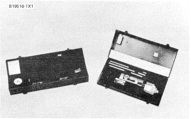
1P3537 DIAL BORE GAUGE GROUP
PROJECTION OF CYLINDER LINERS
Tools Needed: 8B7548 Puller Assembly (Crossbar). Two 2H465 Plates. Two 8F6123 3/4"-16NF Bolts, 140 mm (5.5 In.) long. Four Washers (3/4"-Copper). Four S1575 3/4"-16NF Bolts, 76 mm (3.0 in.) long. 8T455 Liner Projection Tool Group.
145
follows: Check liner projection above the spacer plate as
1. Make sure the top surface of the cylinder block, the liner bores, spacer plates and liner flanges are clean and dry.
2. Install a new gasket and spacer plate (5) on the cylinder block.
3. Install the cylinder liners in the cylinder block without seals or bands.

MEASURING LINER HEIGHT PROJECTION
1. 3H465 Plate. 2. Dial indicator. 3. 1P2402 Gauge Body. 4. S1575 Bolt. 5. Spacer plate. 6. 8B7548 Puller Assembly (Crossbar).
4. Hold the spacer plate and liner in position as follows: a. Install four bolts (4) and washers around each cylinder liner as shown. Tighten the bolts evenly to a torque of 95 N-m (70 lb. ft.).
b. Install crossbar (6), plates (1) and the two 8F6123 Bolts. Be sure the crossbar is in position at the center of the liner and the liner surface is clean. Tighten the bolts evenly to a torque of 70 N-m (50 lb. ft.).


