3 minute read
Pneumatic Speed Control


8S2328 DIAL INDICATOR GROUP INSTALLED
NOTE: Write the dial indicator measurements with their positive (+) and negative (-) notation (signs). This notation is necessary for making the calculations in the chart correctly.
Advertisement
3. Divide the measurement from Step 2 by 2. Write this number on line 1 in columns (B) & (D).
4. Turn the crankshaft to put the dial indicator at (A). Adjust the dial indicator to "O" (zero).
5. Turn the crankshaft counterclockwise to put the dial indicator at (B). Write the measurements in the chart.

CHECKING BORE RUNOUT OF THE FLYWHEEL HOUSING
6. Turn the crankshaft counterclockwise to put the dial indicator at (C). Write the measurement in the chart.
7. Turn the crankshaft counterclockwise to put the dial indicator at (D). Write the measurement in the chart.
CHART FOR DIAL INDICATOR MEASUREMENTS
Position of dial indicator Line No. A B C D Correction for bearing clearance I 0 Dial Indicator Reading II 0 Total of Line 1 & 2 III 0 •• • •• *Total Vertical eccentricity (out of round).
**Subtract the smaller No. from the larger No. The difference is the total horizontal eccentricity.
A10234X5
147
8. Add lines I & II by columns.
9. Subtract the smaller number from the larger number in line III in columns (B) & (D). The result is the horizontal eccentricity (out of round). Line III, column (C) is the vertical eccentricity.
10. On the graph for total eccentricity, find the point of intersection of the lines for vertical eccentricity and horizontal eccentricity.
11. If the point of intersection is in the range marked "Acceptable", the bore is in alignment. If the point of intersection is in the range marked "Not Acceptable", the flywheel housing must be changed.
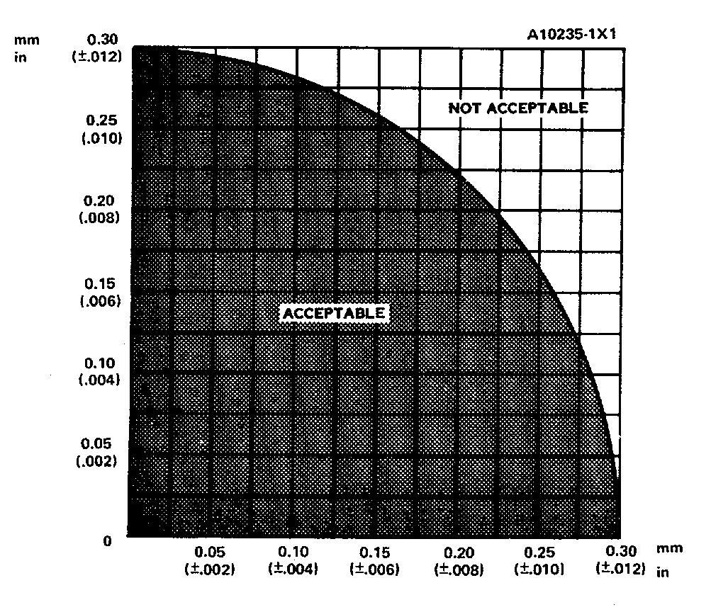
GRAPH FOR TOTAL ECCENTRICITY
Face Runout (axial eccentricity) of the Flywheel
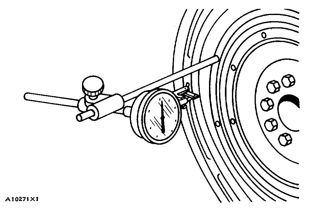
1. Install the dial indicator as shown. Always put a force on the crankshaft in the same direction before the indicator is read so the crankshaft end clearance (movement) is always removed.
CHECKING FACE RUNOUT OF THE FLYWHEEL
2. Set the dial indicator to read "0" (zero).
3. Turn the flywheel and read the indicator every 90 .
4. The difference between the lower and higher measurements taken at all four points must not be more than 0.15 mm (.006 in.), which is the maximum permissible face runout (axial eccentricity) of the flywheel.
Bore Runout (radial eccentricity) of the Flywheel
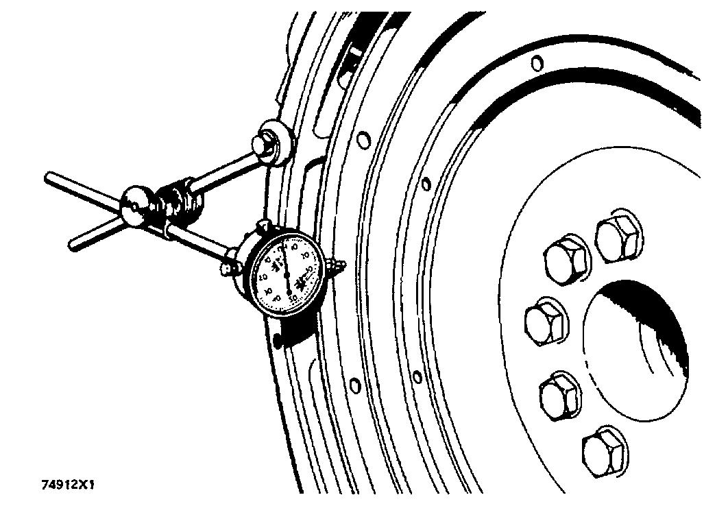
1. Install the dial indicator (3) and make an adjustment of the universal attachment (4) so it makes contact as shown.
2. Set the dial indicator to read "0" (zero).
3. Turn the flywheel and read the indicator every 90 .
4. The difference between the lower and higher measurements taken at all four points must not be more than 0.15 mm (.006 in.), which is the maximum permissible bore runout (radial eccentricity) of the flywheel.
5. Runout (eccentricity) of the bore for the pilot bearing for the flywheel clutch, must not exceed 0.13 mm (.005 in.).
CHECKING BORE RUNOUT OF THE FLYWHEEL 1. 7H1945 Holding Rod. 2. 7H1645 Holding Rod. 3. 7H1942 Indicator. 4. 7H1940 Universal Attachment.

CHECKING FLYWHEEL CLUTCH PILOT BEARING BORE

CHECKING CRANKSHAFT DEFLECTION (BEND)
The crankshaft can be deflected (bent) because the installation of the engine was not correct. If the engine mounting rails are not fastened correctly to the foundation mounting rails, the cylinder block can twist or bend and cause the crankshaft to deflect. This deflection can cause crankshaft and bearing failure.


