4 minute read
3500 Series Engines


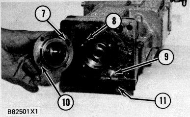
OIL PUMP INSTALLATION 7. Roll pin. 8. Reference hole for roll pin. 9. Plug. 10. Location hole for roll pin to change pump rotation. 11. Strap to hold plug in position when pump housing is removed.
To change the direction of pump rotation do the following steps:
The pump housing holds plug (9) in position. There is spring force on the plug. To prevent injury, mechanically hold plug (9) in the governor housing when the pump housing is removed.

1. Remove the four bolts that hold the pump in place.
2. Use two screwdrivers to lift the pump housing and O-ring seal from the governor.
3. Pull roll pin (7) from the pump housing flange and install it in location hole (10) in the opposite side of the flange.
4. Turn the pump housing and make an alignment of roll pin (7) and reference hole (8) in the governor base.
5. Put a new seal on the oil pump housing. Put clean engine oil on the seal and install the assembly part way into the bore in the base of the governor.
6. Make sure the external pump drive spline is in correct alignment with the internal coupling spline. If the splines are not in alignment, damage to the governor will be the result when the pump housing bolts are installed and tightened. 7. Use a soft faced hammer and hit the outer pump drive shaft so the pump snaps (moves suddenly) in place.
8. Install the four bolts and tighten them to a torque of 10 N-m (90 lb. in.).
9. Make sure the drive shaft turns freely after the bolts have been tightened.
181 GOVERNOR PREPARATION
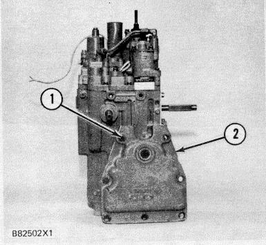
INSTALL COVER ON GOVERNOR 1. Location for bolt. 2. Cover.
Because of the close clearance between the fuel control linkage cover and governor, the upper left hand bolt must be installed at location (1) before cover (2) is put on the terminal shaft and the governor is bolted to the drive adapter housing. The other bolts can be put in place after the governor is in position on the engine.
Put clean engine oil on the lip of the seal and install cover over the governor terminal shaft.
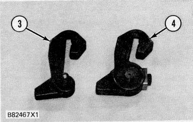
CONTROL LEVERS 3. Lever. 4. Lever.
There are two control levers for the 3161 Governor used on 3500 Series Engines. Lever (3) has a fixed pin and lever (4) has an adjustable pin. The fixed pin lever (3) is used on the 3161 Standard and Generator Set Governors.
The adjustable pin lever (4) is used on 3161 Governors with torque rise. Lever (4) is used to synchronize governor torque rise set point (balance point) position to engine fuel setting position.
The adjustable pin lever (4) can be used on a right hand or left hand mounted governor. To convert the lever from right hand governor use to left hand governor use, remove the lock bolt and lock from the adjustable pin. Remove the adjustable pin from the lever, turn it around and install it into the lever the opposite way. Install the lock and bolt into the adjustable pin and tighten just enough to hold it in place. The lever can now be used on the other end of the terminal shaft for left hand mounted governors.
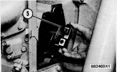
ALIGNMENT OF CONTROL LEVER 5. Notch in fuel control linkage stop lever.
The lever and pin (fixed or adjustable) connect the governor terminal shaft to the fuel control linkage stop lever. The lever pin moves in notch (5) of the stop lever, this causes the two to move together.
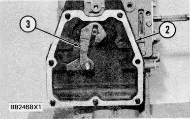
INSTALL LEVER 2. Cover. 3. Lever.
The 3161 Standard and Generator Set Governors with fixed pin levers do not require any special adjustments or setting when installed on the engine. After fuel control linkage cover (2) is in position, install lever (3) on the governor terminal shaft and tighten the bolt to a torque of 25 ± 7 N-m (18 ± 5 lb. ft.). Control levers will go on only the correct way because of the flat and groove of the terminal shaft and the lever pin. This control lever is for right-hand mounted governors. On control levers for left-hand mounted governors, the pin is reversed.
182 INSTALL LEVER 4. Lever. 6. Bolt.
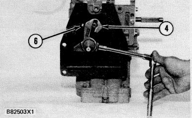
For 3161 Governors with torque rise, the adjustable pin control lever is installed on the terminal_ shaft. Bolt (6) is then tightened to a torque of 25 ± 7 No m (18 ± 5 lb. ft.).
Before the governor is installed on the engine, tighten the pin lock bolt enough to hold the pin in position when the governor is installed on an engine.
After the governor is installed on an engine, the adjustable pin is turned to synchronize the governor travel to the fuel control linkage. See Governor Installation for the correct adjustment and setting of these governors.


