
5 minute read
Air Intake Shutoff


INSTALL DIAL INDICATOR
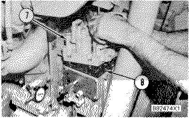
1. Synchronizing pin. 5. 6V3075 Dial Indicator. 6. Fuel setting cover.
5. Put dial indicator (5) with the 5P7263 Contact Point in the 5P4814 Collet. Install dial indicator (5) and the collet in the threaded hole for plug (3). When the contact point seats against the fuel stop lever, slide the dial indicator in or out until it reads zero. Now tighten the collet just enough to hold dial indicator (5) at this position.
REMOVE GOVERNOR TOP COVER 7. Cover. 8. Gasket.
6. Remove the bolts that hold cover (7) in position. Lift cover (7) off the governor and remove gasket (8).

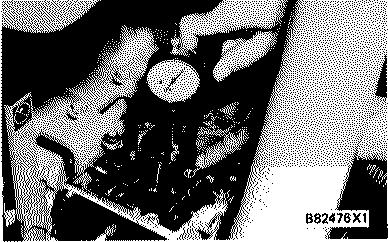
INSTALL DIAL INDICATOR 9. 6V3075 Dial Indicator. 10. 9S228 Bracket Assembly. 11. 3S3269 Contact Point. 12. Bo8t.
7. Install dial indicator (9) on the top of the governor housing with bracket assembly (10) as follows:
Use a top cover bolt with three washers (as spacers under the bolt head) on it and put the bolt through the fixed diameter hole in the bracket. Fasten the bracket to the left side of the housing in the second threaded hole from the front. Put the dial indicator in the adjustable hole in the bracket assembly and position it so the indicator contact point (11) rests on the bolt head (12) of the torque control lever.
8. Check to make sure the cam follower is on the base circle of the governor torque rise cam. See Systems Operation section for a description of the base circle.
9. Move dial indicator (9) until it reads zero and fasten it in place.
10. Turn the synchronizing pin out of the engine front drive housing a minimum of half-way. As the synchronizing pin is backed out, dial indicator (5) will follow the fuel control linkage movement until the fuel control linkage stop lever contacts the fuel setting screw. Dial indicator (5) now shows the torque rise fuel setting. Make sure the torque rise fuel setting is correct. If not, an adjustment is necessary.
11. Look in the Fuel Setting and Related Information Fiche for the full load setting for the engine you are adjusting.
12. Turn the synchronizing pin in until dial indicator (5) reads the full load fuel setting. The full load setting is a reference position and is a temporary setting used to adjust the torque rise cam position.
The purpose of this procedure is to hold the fuel control linkage at the full load setting while the torque rise cam is adjusted.
13. Dial indicator (9) must read 1.00 + 0.05 mm, if it does not, an adjustment is needed. Loosen the bolt that holds the cam enough so the cam can be moved, but keep the bolt tight enough to provide a small drag on the cam.
14. Slide the cam to cause the torque control lever and dial indicator contact to lift 1.00 + 0.05 mm.
15. Tighten the bolt while the cam is held in place. This adjustment of 1.00 + 0.05 mm positions the torque control lever so the torque rise (additional fuel) begins to occur at the correct engine speed.
190
TORQUE RISE CAM ADJUSTMENT
16. Check the cam position by lifting and lowering governor torque arm tool (4) on the terminal shaft. The dial indicator (9) should return to the 1.00 + 0.05 mm setting. If it does not, repeat the adjustment procedure and check again.
The following is an example of this torque rise cam setting. If the engine were running at a rated 1800 r/min with a load, the fuel control linkage would be at full load position and the torque rise cam follower would have lifted 1.00 mm. Torque rise would not have occurred, but would be at the starting point. Should more load be added, the engine speed would decrease. As the speed drops, the terminal shaft and torque rise cam will move and lift the torque rise pilot valve lever beyond the 1.00 + 0.05 mm set point. This will lift the pilot valve and provide additional fuel to the engine and give torque rise greater than the natural torque rise of the engine.
As more load is applied, engine speed will decrease. The fuel control linkage will continue to move in the "FUEL ON" direction, increasing the fuel rate until the fuel control linkage stop lever contacts the fuel setting screw. This is the torque rise fuel setting, and is maximum travel.
17. With the torque rise cam setting made, remove the dial indicator and bracket assembly and install the gasket and top cover on the governor.
NOTE: Make sure the air fuel ratio control limit lever is engaged correctly in the notch of the governor housing before the top cover is installed.
18. Remove dial indicator (5) and the collet. Remove synchronizing pin (1) and install it with the washer to hold the fuel setting cover.
19. Install the two plugs on each side of the fuel setting cover.
191
AUXILIARY CONTROLS
ELECTRIC SHUTDOWN

The shutdown lever in the electric shutdown assembly is adjusted up or down to keep the shutdown/ limit rod in the correct position until the shutoff solenoid is activated.
1. Install the gasket and electric shutdown on top of the governor. Tighten the bolts to 10 Nom (90 lb. in.).
2. Remove the cover, manual shutdown or pressure shutdown, if so equipped, from the top of the electric shutdown assembly.
3. Turn the adjustment screw until the shutdown plunger is even with the top of the gasket for the cover or other shutdowns.
4. Install the cover, manual shutdown or pressure shutdown, if so equipped.
PNEUMATIC SPEED SETTING CONTROL ADJUSTMENTS
The pneumatic speed setting control has two adjustments. One is the speed range bellows adjustment made by turning the bellows (1) inside the bellows housing to increase or decrease the speed range.
PNEUMATIC SPEED SETTING CONTROL 1. Bellows. 2. Plug over low idle adjustment screw.
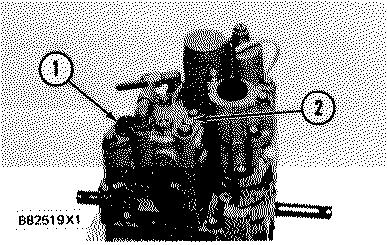
The other is the pneumatic speed level ratio (bias spring) adjustment, made by removing plug (2) and turning the adjustment screw with a 1/8 inch hex wrench.
Pneumatic Speed Level Ratio Adjustment

ADJUSTMENT OF LOW IDLE
When the speed level adjusting screw is turned the low speed setting of the pneumatic control is changed.
With the plug removed, put a 1/8 in. hex wrench in the hole until it engages with the adjustment screw. Turn the screw clockwise to decrease the low idle setting. Turn the screw counterclockwise to increase the low speed setting.
Feedback Spring
To use the pneumatic speed setting control with different air pressure ranges and engine speed settings the feedback spring must be changed.


