
11 minute read
Flywheel Housing Runout Alternators and Regulators.......................Deleted


WATER TEMPERATURE REGULATORS
Temperature when completely open......... 2°C (197° F)
Minimum opening distance at 92°C (197° F) .......9 53 mm (.375 in.)
BELT SIZE WIDTH BELT TOP WIDTH TOP OF PULLEY GROOVE V-BELT TENSION CHART
BELT TENSION “INITIAL”* BELT TENSION “USED”**
GAUGE READING GAUGE READING BORROUGHS GAGUE NUMBERS
mm in. mm. in. N lb. N lb. OLD GUAGE NO. NEW GAUFE NO
3/8 10.7 2 .422 9.65 .380 445±2 2 100± 5 400±2 2 90±5 BT-33-73F BT-33-95
½ 13.8 9 5V 15.8 8 .547 12.70 .500 534±2 2 .625 15.24 .600 534±2 2 120± 5 120± 5 400±4 4 400±4 4 90±1 0 90±1 0 BT-33-96-4-16 BT-33-95
BT-33-72-4-15 BT-33-72C
11/16 17.4 8 .688 15.88 .625 534±2 2 120± 5 400±4 4 90±1 0 BT-33-72-4-15 BT-33-72C
¾ 19.0 5 .750 17.53 .690 534±2 2 120± 5 400±4 4 90±1 0 BT-33-72-4-15 BT-33-72C
15/16 23.8 3 .938 22.30 .878 534±2 2 120± 5 400±4 4 90±1 0 BT-33-72-4-15 BT-33-72C
MEASURE TENSION OF BELT FARTHEST FROM THE ENGINE "'INITIAL" BELT TENSION is for a new belt. **""USED" BELT TENSION is for a belt which has more than 30 minutes of operation at rated speed of engine. A10232-1 X1
NOTE: FOR TORQUE VALUES NOT GIVEN, SEE THE FIRST 33 PAGE OF SPECIFICATIONS FOR GENERAL TIGHTENING TORQUES
33
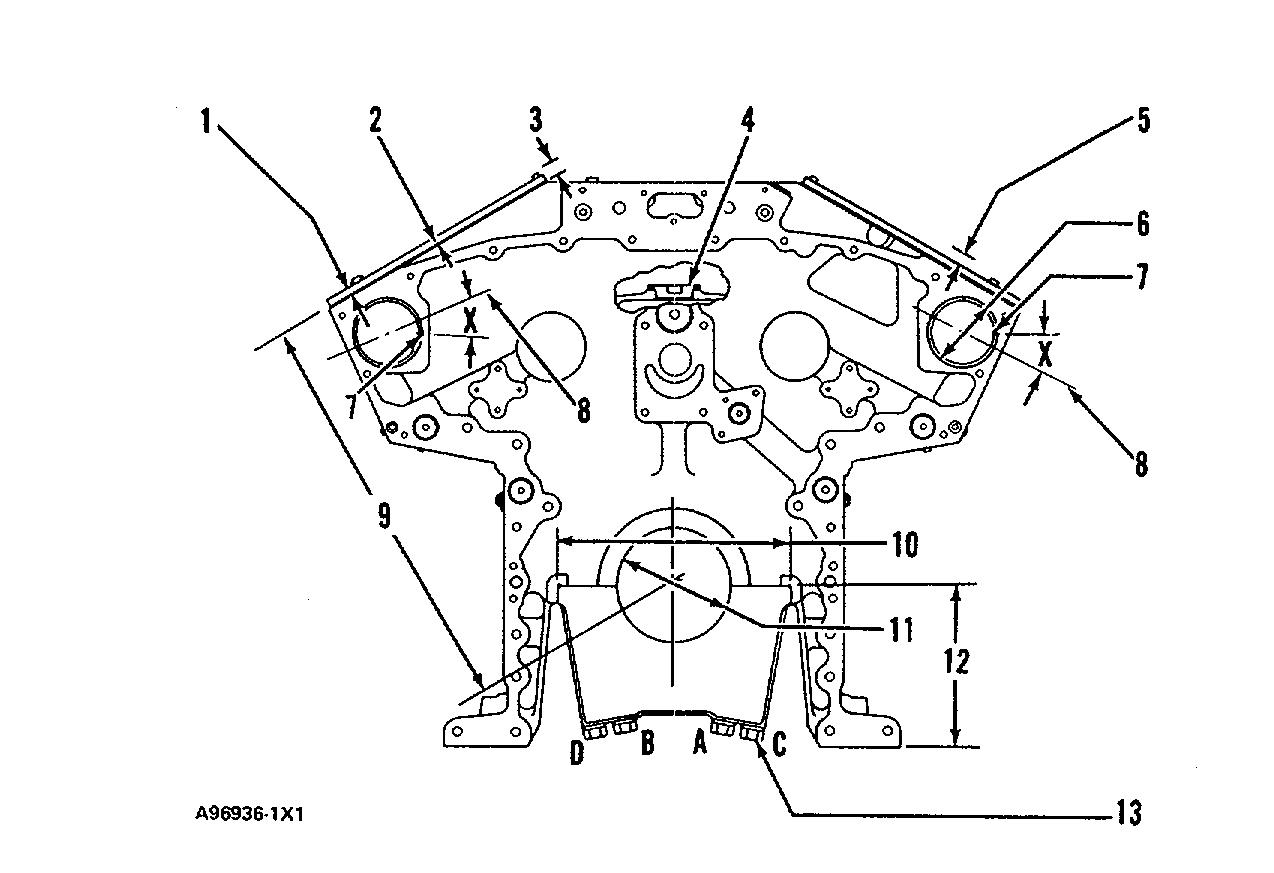
(1) Thickness of spacer plates....................2.313 ±0.025 mm (.4848 ± .0010 in.)
(2) Thickness of gasket between the cylinder block and spacer plates................0.208 ± 0.025 mm (.0082 ± .0010 in.)
(3) Distance all dowels extend above block face.........20.0 ± 0.5 mm (.79 ±.02 in.)
(4) Torque for plugs....100 ± 15 N-m (75 ± 11 lb. ft.)
(5) Make reference to CYLINDER LINER PROJECTION, for the height of the liner.
(6) Bore in the block for the camshaft bearings ........92.000 ± 0.020 mm (3.6220 ± .0008 in.)
(7) Camshaft bearing junction.
(8) Centerline through oil holes in camshaft bearings. Oil holes must be positioned from horizontal at angle "X"20 ± 5°
NOTE: All bearing oil hole centerlines (8) and bearing junctions (7) must be in position shown for each side of cylinder block.
(9) Dimension (new) from centerline of crankshaft bearing bore to top of block (top deck)........ 586.00 mm (23.071 in.)
(10) Width of main bearing cap.....................340.000 ± 0.015 mm (13.3858 ±. 0006 in.)
Width of cylinder block for main bearing cap........340.000 ± 0.015 mm (13.3858 ± .0006 in.)
Clearance between the sides of the main bearing cap and the cylinder block..................0.030 mm (.0012 in.) tight to 0.030 mm (.0012 In.) loose
(11) Bore in the block for the main bearings:
Standard, original size (new)..................69.742 ± 0.020 mm (6.6828 ±.0008 in.)
0.63 mm (.025 in.) larger than original size....................170.372 ± 0.020 mm (6.7076 ±. 0008 in.)
(12) Dimension (new) from centerline of crankshaft bearing bore to bottom of block (pan rails)..............................230.00 mm (9.055 in.)
(13) Tighten the bolts that hold the caps for the main bearings as follows: Install main bearing caps with "FRONT" and cast part number toward front of the block. Each cap has a number and must be installed in the same position as the correct number on the side of the cylinder block pan rail.
a. Before assembly, put Fel-Pro C100 Lubricant (if not available, use 2P2506 Thread Lubricant) on the bolt threads and all surfaces that make contact between the bolt and the cap.
b. Tighten the bolts in letter sequence to............. 136 ± 14 N•m (100 ± 10 lb. ft.)
c. Tighten the bolts in letter sequence more180±50
(14) Distance dowel extends from rear face of block..............6.0 ± 0.5 mm (.24 ±.02 in.)
(15) Torque for adapter................... 100 ± 15 N-m (75 ± 11 lb. ft.)
(16) Distance dowels extend from front face of block..............6.0 ± 0.5 mm (.24 ± .02 in.)
FRONT VIEW OF CYLINDER BLOCK
(17) Distance dowels extend from rear face of block...19.0 ± 0.5 mm (.75 ± .02 in.)
(18) Distance dowels extend from front face of block.......40.0 ± 0.5 mm (1.58 ±.02 in.)

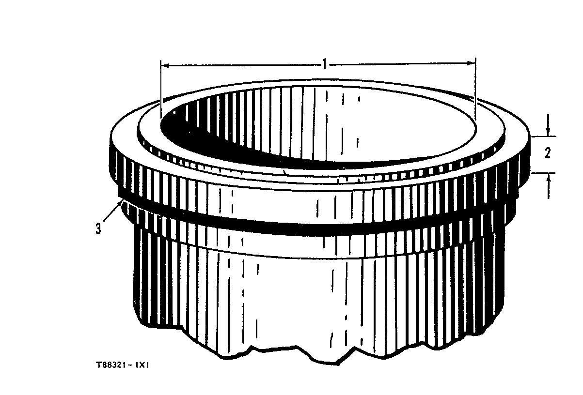
CYLINDER LINERS
For Installation a. Put liquid soap on cylinder block liner bore surfaces and rubber seals on the lower part of the liner.
b. Put the filler band completely in clean engine oil for a moment.
c. Install filler band (3) in the groove under the liner flange, without delay.
d. Install the liner in the bore immediately, before expansion of the filler band.
(1) Bore in liner (new).......................170.025±0.025 mm (6 6939 ± 0010 in.)
(2) Thickness of flange on liner............ 12.65 ± 0.02 mm (.498 ± 001 in )
(3) Filler Band.
CYLINDER LINER PROJECTION
Make reference to CYLINDER LINER PROJECTION in Testing and Adjusting for the complete procedure.
1. Install the gasket and spacer plate (5).
Install copper washers and bolts (4) to hold the spacer plate Tighten bolts (4) evenly in four steps. 1st step..................14 N•m (10 lb. ft.)
2nd step.................35 N•m (25 lb. ft )
3rd step...................70 N•m (50 lb. ft )
4th step...................95 N•m (70 lb. ft )
2. Install tooling as shown. Tighten bolts for crossbar evenly in four steps.
1st step..................... 7 N•m (5 lb ft.)
2nd step....................... 20 N•m (15 lb ft )
3rd step..........................35 N•m (25 lb ft.) 4th step........................ 70 N•m (50 lb ft.) 3. Measure cylinder liner projection with dial indicator (2) in 1P2402 Gauge Body (3) as shown Measure at four places around each cylinder liner near the clamped area
Average of four projection measurements from any cylinder liner must be..........................0.059 to 0 199 mm (.0023 to .0078 in.)
Maximum permissible difference between all four measurements..........0.05 mm (.002 in.)
(1) 3H465 Plate
(6) 8B7548 Push-Puller Crossbar.

NOTE: FOR TORQUE VALUES NOT GIVEN, SEE THE FIRST35 PAGE OF SPECIFICATIONS FOR GENERAL TIGHTENING TORQUES
Width of groove in piston for piston ring (new)
Thickness of piston ring (new).
Clearance between groove and piston ring (new).
Clearance between ends of piston ring when installed in a cylinder liner with a bore size of 170 mm (6.694 in )
Increase in clearance between ends of piston ring for each 0 03 mm in ) increase in cylinder liner bore size
PISTONS AND RINGS
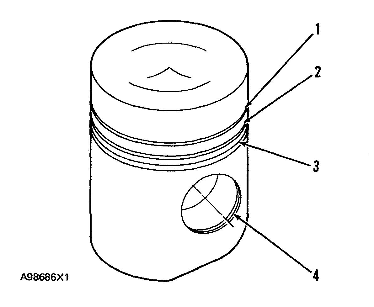
PISTONS AND PISTON RINGS (1) TOP RING* (2) INTERMEDIATE RING* (3) OIL CONTROL RING**(with 17 oil slots) (3) OIL CONTROL RING**(with 12 oil slots)
5.050 ± 0.013 mm 5 050 ± 0.013 mm
0.80 ± 0.20 mm (.031 ± .008 In, ) 0 80 ± 0.20 mm (.031 ± 008 in.) (.1988 ± .0005 in ) (.1988 ± .0005 in.) 4.968 ±0.013 mm 4.954 ± 0 019 mm
(.1956 ± 0005 in.) (.1950 ±0007 In ) 0.082 ±0 013 mm 0 064 to 0 128 mm
(0032 ±.0005 In.) ( 0025 to .0050 in.) 0 56 ±12 mm (.022 ±005 In.) 0 70 ± 0.19 mm (.028 ± 007 in )
(.0010 08 mm ( 003 in )
*Install piston ring with "UP" side toward top of piston.
NOTE: Top Ring (1) has the mark "UP-1." Intermediate Ring (2) has the mark "UP-2."
**Install Oil Control Ring (3) with the gap in the spring 180° away from the gap in the ring. White portion of spring must be visible at the ring end gap.
(4) Bore in piston for pin............................... 69.983 + .008 mm (2.7552 + .0003 in.)
Clearance between pin and bore in piston............................ 0.008 to 0.034 mm (.0003 to .0013 in.)
Pin diameter........................ 69.962 ±.005 mm (2.7544 ±.0002 in.)
36
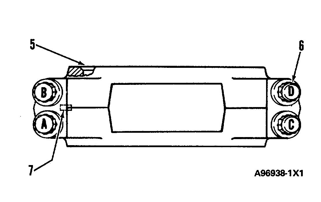
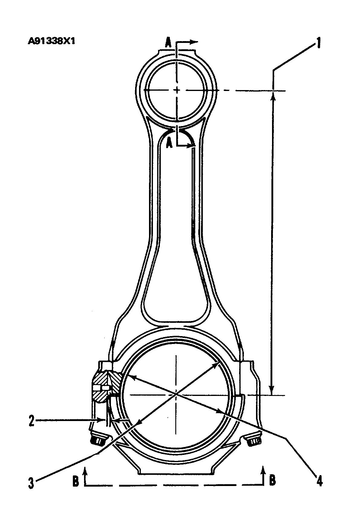
CONNECTING RODS
(1) Distance between center of bearings..................380.00 mm (14.961 in.)
(2) Distance that locating pin extends from rod cap..... 4.0 ± 0.5 mm (.16 ±.02 in.)
(3) Bore in connecting rod for bearing with bolts tightened to specifications (6)...........143.028 ± 0.015 mm (5.6310 ± .0006 in.)
(4) Take the connecting rod bearing measurements on the centerline of the connecting rod bores.
Bore in bearing for crankshaft....................................135.133 to 135.194 mm (5.3202 to 5.3226 in.)
Clearance between bearing and crankshaft (new)............ 0.107 to 0.218 mm (.0042 to .0086 in.)
(5) Side of connecting rod with chamfer.
(6) Tighten connecting rod bolts as follows:
NOTE: Bolts A and B are on the same end of the rod cap that has bearing tabs and location pin (7).
a. Before assembly, put Fel-Pro C100
Lubricant (if not available, use 2P2506
Thread Lubricant) on the bolt threads and all surfaces that make contact between the bolt and the cap.
b. Tighten bolts A and B to....................90 ± 5 N•m (65 ± 4 lb. ft.)
c. Tighten bolts C and D to .......90 ± 5 N•m (65 ±4 lb. ft.)
d. Tighten bolts A and B again to...... 90 ±5 N•m (65 ± 4 lb. ft.)
e. Tighten bolts C and D again to...........90 ± 5 N•m (65 ± 4 lb. ft.)
f. Tighten each bolt more.........90 ± 5° (7) Location pin for correct installation of connecting rod caps.
(8) Bore in bearing for piston pin (new).......70.000 ± 0.008 mm (2.7559 ±.0003 in.) Diameter of piston pin (new)........69.962 ± 0.005 mm (2.7544 ±. 0002 in.) NOTE: Connecting rod must be heated for installation of piston pin bearing. Do not use a torch. Heat connecting rod to a temperature of 177 to 204° C (350 to 400° F)
Side clearance between two connecting rods on same crankshaft pin (new): 3508............ 0.900 ± 0.282 mm (.0354 ± .0111 in.) 3512.......... 0.850 ± 0.232 mm (.0335 ± .0091 in.) 3516.......... 0.850 ± 0.332 mm (.0335 ± .0131 in.)

NOTE: FOR TORQUE VALUES NOT GIVEN, SEE THE FIRST PAGE OF SPECIFICATIONS FOR GENERAL TIGHTENING TORQUES
CONNECTING ROD AND MAIN BEARING JOURNALS
CONNECTING ROD BEARING JOURNALS 0.63 mm (.025 in.) 1.27 mm (.050 in.) UNDERSIZE UNDERSIZE
ORIGINAL SIZE (SMALLER) (SMALLER)
JOURNAL JOURNAL JOURNAL
Diameter of crankshaft journal (bearing surface) 135 000 ± 0.025 mm 134.370 ± 0.025 mm 133.730 ± 0 025 mm
for connecting rod (5.3150 ± 0010 in.) (5.2902 ± .0010 in.) (5.2650 ±.0010 in.)
Clearance between bearing 0.107 to 0.218 mm
and journal (new). (.0042 to 0086 in.)
MAIN BEARING JOURNALS 0.63 mm (.025 in.) 1.27 mm (.050 in.) UNDERSIZE UNERSIZE ORIGINAL SIZE (SMALLER) (SMALLER)
JOURNAL JOURNAL JOURNAL
Diameter of crankshaft journal (bearing surface) for main 160.000 ± 0.025 mm 159.370 ± 0 025 mm 158 730 ± 0 025 mm bearings. (6.2992 ± 0010 in.) (6.2744 ± .0010 in.) (6.2492 ± .0010 In.)
Clearance between bearing and 0.122 to 0.241 mm
journal (new) (.0048 to .0095 in.)
38
CRANKSHAFT
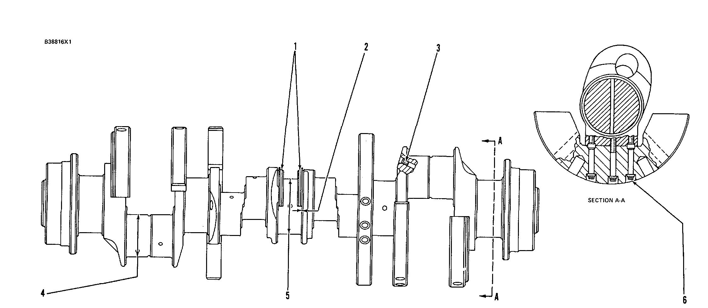
(3508)
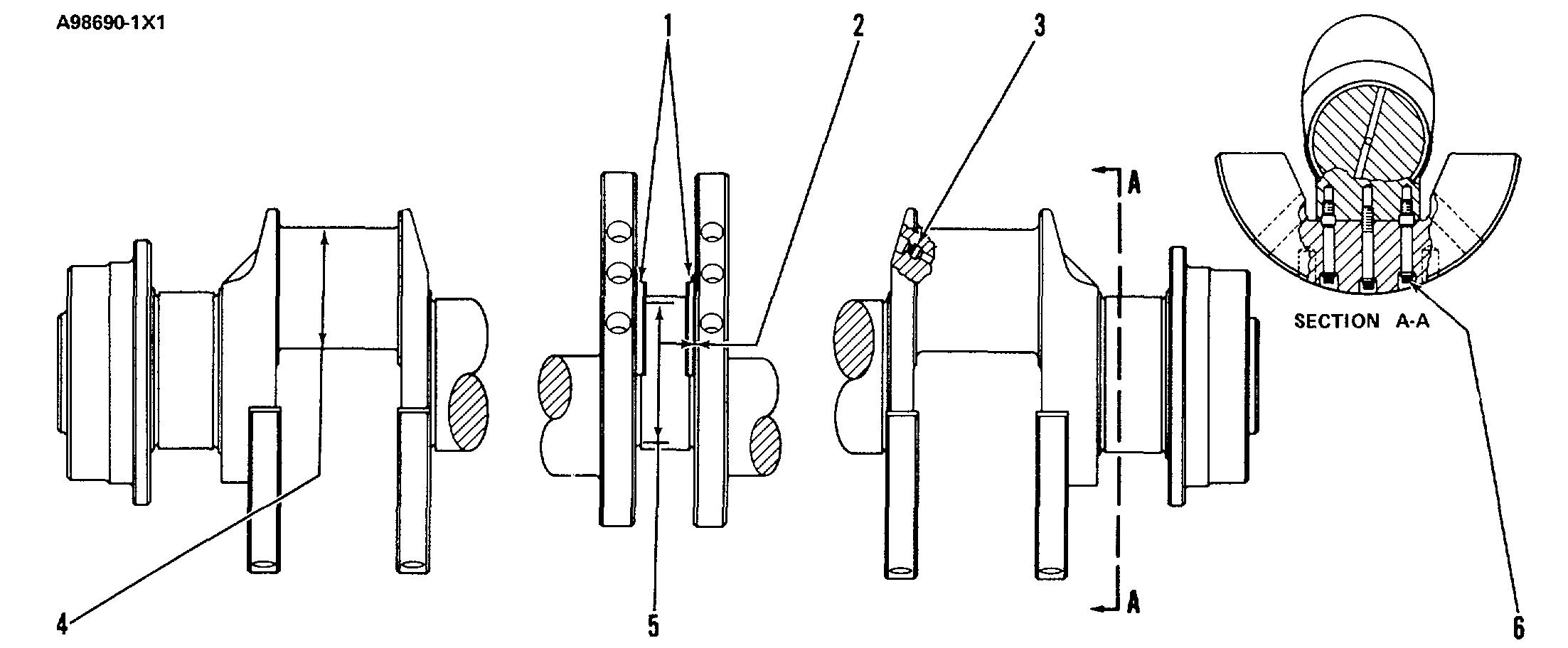
(3512 & 3516)
(1) Thrust plates for center bearing only.
(2) End play for the crankshaft (new) ......0.170 to 0.630 mm (.0067 to .0248 in.)
(3) Plugs.
Earlier:
Torque for 1/4 pipe thread plugs ....... 25 N•m (20 lb. ft.) min
"Stake" (make a mark with a punch) the crankshaft to hold the pipe plugs tight.
Later:
Torque for straight thread plugs .......50 ± 7 N•m (37 ± 5 lb. ft.)
(4) Make reference to Connecting Rod Bearing Journals. (5) Make reference to Main Bearing Journals.
(6) Procedure to tighten counterweight bolts:
a. Before assembly, put Fel-Pro C100
Lubricant (if not available, use 2P2506
Thread Lubricant) on the bolt threads, shank, and underside of bolt head.
b. Tighten the bolts evenly to......... 50 ±5
N•m (37 ± 4 lb. ft.)
c. Tighten each bolt more.........120 ± 5°
NOTICE Each counterweight has a number and must be installed in the same position as the correct number on the crankshaft mounting pad to prevent damage to the crankshaft when the engine is run.
NOTE: FOR TORQUE VALUES NOT GIVEN, SEE THE FIRST PAGE OF SPECIFICATIONS FOR GENERAL TIGHTENING TORQUES
39
CRANKSHAFT WEAR SLEEVES AND SEALS
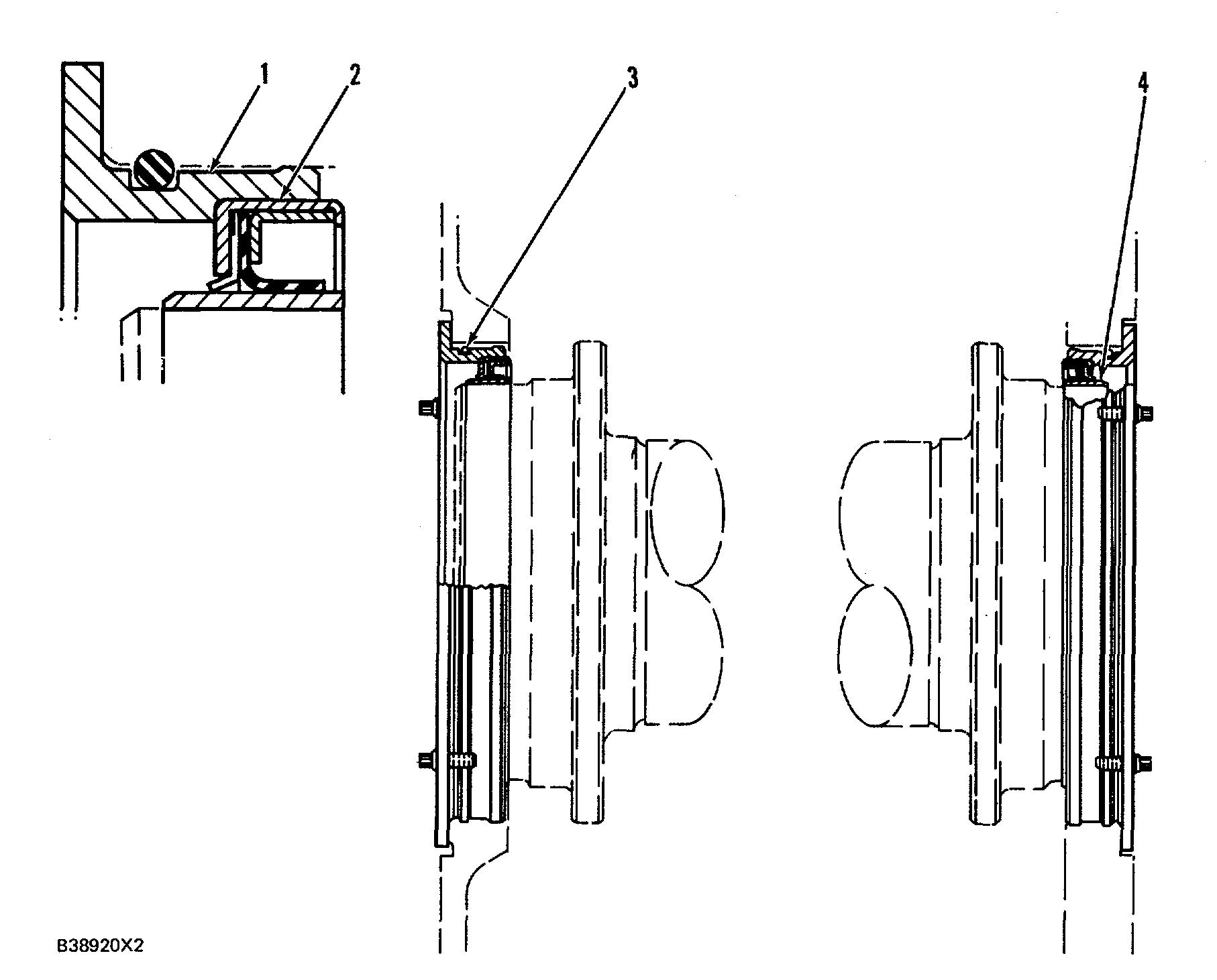
(1) Adapter.
(2) Crankshaft seals:
Crankshaft seals must be installed with the lip of the seal toward the inside of the engine as shown. Make sure the correct seal is installed on each end of the crankshaft. For SAE Standard Rotation engines use 1W6974 Seal Group on the front and 1W6977 Seal Group on the rear. For SAE Opposite Rotation engines use 1W6977 Seal Group on the front and 1W6974 Seal Group on the rear.
(3) Put clean engine oil on the O-ring seals at assembly.
(4) Wear sleeve.
Removal:
a. Remove the seal adapters from each end of the engine and remove the seals from the adapters.
NOTE: Seals and wear sleeves can not be used again, after the seals and wear sleeves are separated.
b. Remove wear sleeves with 5P7409 Distorter and 6V3143 Distorter Adapter.
Installation:
a. Do not separate wear sleeves (4) from crankshaft seals (2). Once they are separated, they can not be used again. NOTE: For complete procedure with illustrations, make reference to Disassembly and Assembly section of this Service Manual.
b. Install sleeve and seal assembly into adapter (1) with correct tools.
c. Clean the outer surface of the crankshaft and the inner surface of wear sleeve (4) with 6V1541 Quick Cure Primer.
d. Carefully put a thin coat of 9S3265
Retaining Compound on the inner surface of wear sleeve (4) and on crankshaft surface.
e. Install adapter (1), seal (2) and wear sleeve (4) as a unit on the end of the crankshaft with the correct tools.
Tools Needed
6V4002 Forcing Bracket (2) 6V4001 Forcing Ring (1) 1B4330 Nut (5/16"-18 NC) (4) 6V4003 Locator (1) 2N5006 Bolt (1"-14 NF x (2) 2 5 in. long) Guide Bolts (5/16"-(2) 18 NC x 4 in. long) 6V4977 Installer (1) 9S8858 Nut (1)


