4 minute read
Troubleshooting


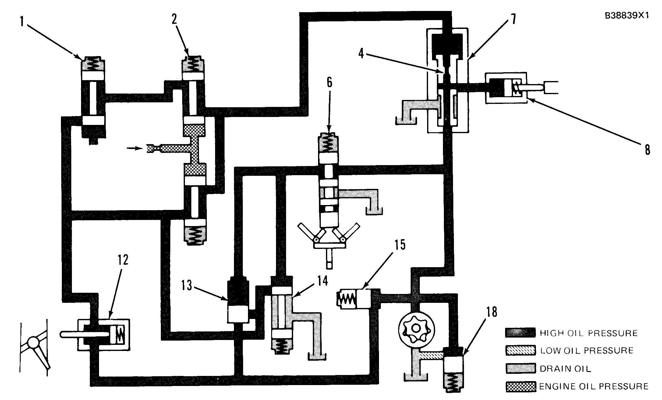
SCHEMATIC NO. 9 (OVERSPEED FAULT) 1. Selector valve. 2. Low speed oil protection valve. 4. Diverter valve orifice. 6. Speed sensing valve spool. 7. Diverter valve. 8. Fuel shutoff actuator 12. Air inlet shutoff actuator 13. Air inlet sequence valve. 14. Pilot operated two-way valve. 15. Fuel shutoff sequence valve. 18. Oil pressure relief valve.
OVERSPEED CIRCUIT (OVERSPEED FAULT)
Advertisement
Make Reference to Schematic No. 9.
When the engine speed is 18% above full load speed, speed sensing valve spool (6) will be moved up by the flyweights. This will send oil to pilot operated twoway valve (14) and to the spring side of air inlet sequence valve (13). The oil pressure will close both valves and oil in the air inlet shutoff system can not go to drain. The oil pressure in the system will i crease until oil pressure relief valve (18) opens at 1720kPa (250psi). The increase pressure will move air inlet shutoff actuator (12), which will release the air inlet shutoff valve. This stops the combustion air supply to the engine. Fuel shutoff circuit oil also can not go to drain. The difference in oil pressure across diverter valve orifice (4) will now go to zero. The valve spool of diverter valve (7) will move down by spring force, which will cause alignment of the ports to fuel shutoff actuator (8). Now, oil pressure in the fuel shutoff circuit will activate fuel shutoff actuator (8), which will cause the governor to move the fuel control linkage to the “SHUTOFF” position.
NOTE: Because the air inlet shutoff is the most positive way to shutdown an engine, air inlet shutoff actuator (12) is activated by the protective system before fuel shutoff actuator (8) is activated.
224
SCHEMATIC NO. 10 (EMERGENCY MANUAL SHUTOFF) 4. Diverter valve orifice. 6. Speed sensing valve spool. 7. Diverter valve. 8. Fuel shutoff actuator. 11. Emergency manual shutoff valve. 13. Air inlet sequence valve. 14. Pilot operated two-way valve. 15. Fuel shutoff sequence valve. 18. Oil pressure relief valve.
EMERGENCY MANUAL SHUTOFF
Make Reference to Schematic No. 10
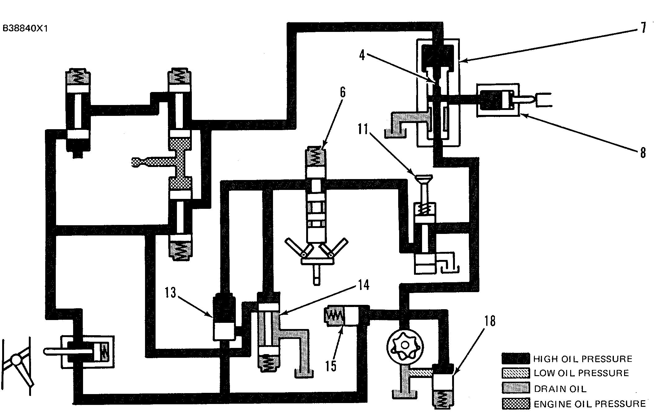
When the knob on emergency manual shutoff ( 11 ) is pulled, system oil flow is directed to pilot operated two-way valve (14) to close the valve. This stops oil flow to drain in both the fuel and air inlet shutoff circuits. The protective system then, shuts down the engine in the same sequence as for an overspeed fault condition. The combustion air supply is stopped and the fuel control linkage is moved to the "SHUT- OFF" position to shutdown the engine.
225
SCHEMATIC NO. 11 (START-UP OVERRIDE) 2. Low speed oil protection valve. 3. Start-up override valve. 4. Diverter valve orifice. 7. Diverter valve. 8. Fuel shutoff actuator. 15. Fuel shutoff sequence valve.
START-UP OVERRIDE OF LOW ENGINE OIL PRESSURE
Make Reference to Schematic No. 11
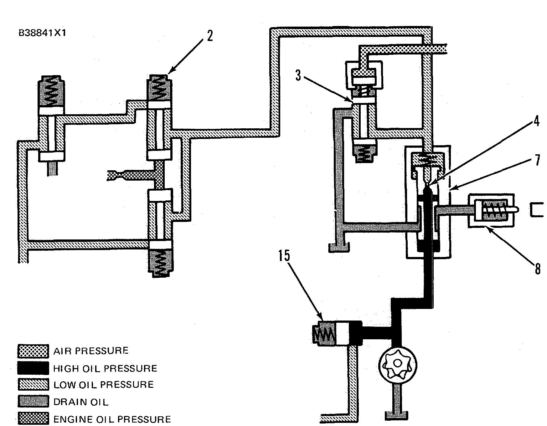
On a hot restart, after severe operating conditions, the engine oil pressure can increase slowly. If the rate of pressure increase is too slow, the protective system activates fuel shutoff actuator (8) to move the fuel control linkage to the "SHUTOFF" position be- cause of a low engine oil pressure fault condition. Therefore, an override of the engine oil pressure circuit is needed in the protective system.
An electric solenoid or air operated start-up override valve (3) is installed in the diverter valve return line. The valve is normally closed. When start-up override valve (3) is operated, the outlet of the diverter valve is connected to drain. This maintains a pressure drop across diverter valve orifice (4) and does not let the diverter valve shift to the shutdown position.
When start-up override valve (3) is not in use, the engine oil circuit is put back into normal operation as in Schematics No. 2 and No. 4.
226

SCHEMATIC NO. 12 (REMOTE NORMAL SHUTOFF) 4. Diverter valve orifice. 7. Diverter valve. 8. Fuel shutoff actuator. 19. Remote normal shutoff valve.
REMOTE NORMAL SHUTOFF
Make Reference to Schematic No. 12.
The remote normal shutoff is an option that can be used with the hydramechanical protective system. An air or electric operated remote normal shutoff valve ( 19) is installed in the diverter valve return line. When remote normal shutoff valve (19) is operated, the outlet of the diverter valve is stopped. The oil pressure becomes equal on both sides of diverter valve orifice (4). Spring force will move the valve spool of diverter valve (7) to make an alignment of the oil passage with the oil line to fuel shutoff actuator (8). Oil pressure can now activate fuel shutoff actuator (8) which causes the governor to move the fuel control linkage to the "SHUTOFF" position and shutdown the engine.227


