3 minute read
Pistons


VALVE SEAT INSERTS, VALVE GUIDES
REMOVE VALVE SEAT INSERTS 1103-11
Advertisement
Tools Needed A 9S3095 Handle Assembly 1 6V4008 Extractor 1 start by: a) remove valves 1. Remove the valve seat inserts from the cylinder head with tooling (A).
2. Clean and remove any burrs from the valve seat bores.
INSTALL VALVE SEAT INSERTS 1103-12
Tools Needed A 9S3095 Handle Assembly 1 6V4008 Extractor 1
1. Lower the temperature of valve seat inserts (1) and install them with tooling (A).
NOTICE Do not make the diameter of the extractor larger when the insert is installed or damage to the insert and cylinder head can be the result.
2. Grind valve seat inserts (1) as to the values given in SPECIFICATIONS. end by: a) install valves
REMOVE VALVES GUIDES 1104-11
Tools Needed A 7M3975 Driver 1 start by: a) remove valves
1. Use tool (A) and a hammer to push the valve guides out of the cylinder head as shown.
INSTALL VALVE GUIDES 1104-12
Tools Needed A 7M3975 Driver 1 5P1729 Bushing 1
1. Put clean engine oil on the outside diameter of the valve guides.
2. Use tooling (A) and install the valve guides until they extend 26 mm (1.024 in.) from the surface of the cylinder head. See SPECIFICATIONS for the correct values for the inside diameters of new and used valve guides. end by: a) install valves
383
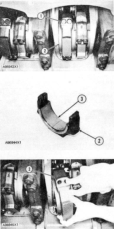
CONNECTING ROD BEARINGS
REMOVE AND INSTALL CONNECTING ROD BEARINGS 1219-10
Tools Needed A 9S9082 Engine Turning Pinion 1 start by: a) remove piston cooling jets 1. Use tool (A) and turn the engine flywheel to move the connecting rod cap bolts into a position for removal.
2. Remove bolts (I) to remove bearing caps (2) from the crankshaft and connecting rod. Remove the lower half of the bearings from caps (2).
3. Push the connecting rods away from the crankshaft and remove the upper halves of the bearings from the rods. NOTE: Install rod bearings dry when the clearance checks are made. Put clean engine oil on the rod bearings for final assembly. 4. Clean the surfaces where the bearing halves fit. Install bearing halves (3) in the rods and caps (2). Put 5P960 Multipurpose Type Grease on the bolt threads and contact surfaces of the bolts and caps.
5. Make a check of the bearing clearance with Plastigage. Put caps (2) in position on the connecting rods and make sure the number on the side of the cap is next to and respective with the number on the side of the connecting rod. Tighten the bolts in the number sequence shown as follows:
NOTICE Do not use an impact wrench to tighten the bolts the additional 90 ± 50 of a turn more.
NOTE: Bolts (6) and (7) are on the end of the rod cap opposite the end that has the location pin for correct installation. a) Tighten bolts No. 4 and 5 to a torque of 90 + 5 N•m (65 + 4 lb. ft.). b) Tighten bolts No. 6 and 7 to a torque of 90 + 5 N•m (65 + 4 lb. ft.). c) Tighten bolts No. 6 and 7 again to a torque of 90 + 5 N•m (65 + 4 lb. ft.). d) Tighten each bolt 90 + 50 of a turn more. 6. Remove the cap and measure the Plastigage. The rod bearing clearance must be 0.107 to 0.218 mm (.0042 to .0086 in.).
7. Put clean engine oil on both halves of the rod bearings. Put caps (2) in position and tighten the bolts as in Step 5. end by: a) install piston cooling jets


