
6 minute read
Gauge Panel


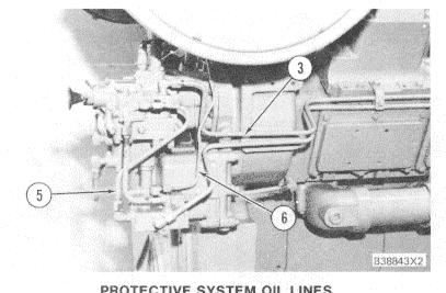
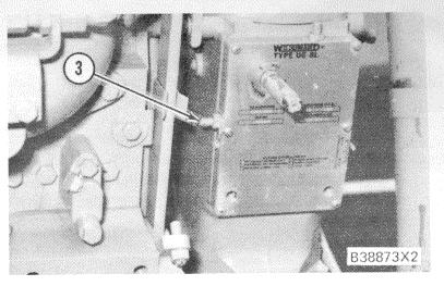
PROTECTIVE SYSTEM WITH ENGINE SHUTDOWN FOR OVERSPEED ONLY, ALARMS FOR OTHER FUNCTIONS (LOP, HWT) 1. Oil line to air inlet shutoff actuator. 2. Return line from air inlet shutoff actuator. 3. Oil line to thermostatic pilot valve. 4. Return line from diverter valve. 5. Oil line to diverter valve. 6. From two-way valve at the diverter valve to drain. 7. From diverter valve to governor (fuel) shutoff actuator. 8. Oil pressure switch for alarms.
PROTECTIVE SYSTEM OIL LINES
Advertisement
3. Oil line to thermostatic pilot valve. 5. Oil line to diverter valve. 6. From two-way valve (at the diverter valve) to drain.
START-UP OVERRIDE VALVE CHECK
On an engine with an air start system, start and operate the engine at low idle. Loosen the drain line from the two-way (palm) valve. There should be no oil present. If there is any oil flow, the valve has failed and replacement is necessary.
AIR INLET SHUTOFF CHECK
Operate the engine at low idle and pull the red, emergency knob. The air inlet shutoff valve must close and stop the engine. Low oil pressure and high coolant temperature alarms should also be activated, if so equipped.
The fuel shutoff actuator must also move the governor and fuel control linkage to the "SHUTOFF" position.
NOTICE
After this test has been performed, the air inlet shutoff valve must be opened. Also, the startup override valve must be operated to release hydraulic pressure from the governor shutoff actuator before the engine can be started again.
244
FUEL SHUTOFF TEST
Hold open the air inlet shutoff valve with a length of wire. (If another person is present, the valve can be held open by hand.) Pull the red, emergency. knob. Since the air inlet shutoff valve has been held open, the fuel shutoff actuator should stop the engine. The low oil pressure, high coolant temperature alarms should also be activated, if so equipped.
NOTICE
Before starting the engine, make sure the air inlet shutoff is reset so the protective system can operate, if needed, and to prevent damage to the engine at start up.
LOW OIL PRESSURE TEST
Disconnect the oil supply line that is installed between the thermostatic pilot valve and the shutoff control group, at the control group. Attach a 3N4847 Hose Assembly to the control. Use a 7D5363 Connector to adapt a 3R3837 Shutoff Valve to the end of the hose.
NOTE: If the engine is not equipped with a thermostatic pilot valve, remove the plug from where line (4) would connect to the shutoff control group.
Close the valve and start the engine and operate it at low idle. The engine will run normally.
Place the end of the hose in a bucket or other container and open the valve to drain approximately onehalf liter (one U.S. pint) of oil to lower the oil pressure.
This will actuate the low oil pressure protection circuit and cause engine shutdown through the fuel shutoff actuator or activate the low oil pressure, high coolant temperature alarms, if so equipped. The air inlet shutoff should not be activated by this test.
NOTE: The fuel shutoff actuator will not be activated in a protective system that gives overspeed protection only, when a low oil pressure fault is simulated.
If the fuel shutoff actuator is not activated by this test, check the actuator, oil lines or electrical connections, and the shutoff control group for defects.
If the alarms fail to activate, make sure the pressure switch on the control valve group, the wiring and alarms work correctly to locate and repair parts as needed. Remove the hose assembly, connector and shutoff valve from the engine. Connect the oil supply to the thermostatic pilot valve.
All of the above tests are performed at low idle. Successful shutdowns and alarms at low idle indicate correct operation. Therefore, it is not necessary to perform the tests at high idle.
SHUTOFF SPEED SETTING ADJUSTMENT
NOTE: When major disassembly or adjustment of the shutoff control group is needed, see CATERPILLAR FUEL INJECTION TEST BENCH BOOK, FORM NO. SEHS7466 for the complete specifications and test bench procedures to use.
NOTICE
A mechanic with training in governor adjustments is the ONLY one that should perform the following procedure. Severe engine damage could occur if this procedure is not followed. Also, check the capabilities of driven equipment to make sure damage will not occur if run at overspeed.
1. Check and make sure the engine fuel settings are correct. See FUEL SETTING CHECK in the Engine TESTING AND ADJUSTING section of this Service Manual.
2. Start the engine and operate it at low idle.

SHUTOFF CONTROL GROUP
1. Emergency manual shutoff. 2. Overspeed setting adjustment bolt.
3. Before any adjustment to the shutoff control overspeed setting is made, check for correct operation of the hydramechanical protective
245
system. Pull emergency manual shutoff knob ( I). Successful shutdown of intake air and fuel indicate correct operation.
NOTICE After the emergency manual shutoff has been operated, the air inlet shutoff valve must be opened. Also, the start-up override must be operated to release hydraulic pressure from the fuel shutoff actuator before the engine can be started again.
4. Remove seal and wire from the bolts and remove the cover from over the high idle adjustment screw on the Caterpillar 3161 Governor, or the seal wire from high idle screw lock nut on Woodward UG-8L Governor.
5. Connect a tachometer of known accuracy to the engine.
NOTE: Some types of engine driven equipment, such as generators, pumps or compressors, can be damaged if operated at 18% above full load speed. If so, the driven equipment must be disconnected from the engine during this test. If this cannot be done, adjustment of the shutoff control group can be made on the CATERPILLAR FUEL INJECTION TEST BENCH. See Form No. SEHS7466 for the complete test bench procedures.
6. Start the engine again and operate it at high idle with no load.
7. Turn the governor high idle adjustment screw slowly to increase engine rpm. The air inlet shutoff must close and the fuel must be shut off through the governor and fuel control linkage at 18% + 25 rpm above full load rpm. For example, this is 2124 + 25 rpm for an engine rated at 1800 rpm.
NOTICE After the hydramechanical protective system has been activated, the air inlet shutoff valve must be opened. Also, the start-up override must be operated to release hydraulic pressure from the fuel shutoff actuator before the engine can be started again.
8. If engine shutdown does not occur at 18% + 25 rpm above full load rpm, slowly increase engine rpm 50 rpm more. For example, this is 2174 rpm for an engine rated at 1800 rpm. If engine shutdown still does not occur, decrease the engine rpm and remove the seal and lockwire and turn overspeed adjusting bolt (2) one turn counter
246 UG-8L GOVERNOR
3. High idle adjustment screw.
clockwise. Again, slowly increase the engine rpm to check for engine shutdown at 18% + 25 rpm above full load rpm.

ADJUSTMENT OF HIGH IDLE ON 3161 GOVERNOR
NOTE: If engine shutdown occurs before 18% + 25 rpm of full load rpm, turn overspeed adjusting bolt (2) clockwise to increase the shutoff control group overspeed setting.
9. Repeat the above procedure until engine shutdown occurs at the correct rpm.
10. Adjust engine high idle to the specifications shown on the Engine Information Plate which is attached to one of the right side camshaft inspection covers. If the Engine Information Plate is missing, see the FUEL SETTING AND RELATED INFORMATION FICHE for the correct specifications to use.
11. Install the seals and lockwires for the shutoff control group and the governor high idle adjustment screw.


