2 minute read
Woodward UG8 Lever Governors


FLYWHEEL HOUSING
Make reference to FLYWHEEL HOUSING RUNOUT and FLY-WHEEL HOUSING BORE for the correct methods of flywheel housing inspection
Advertisement
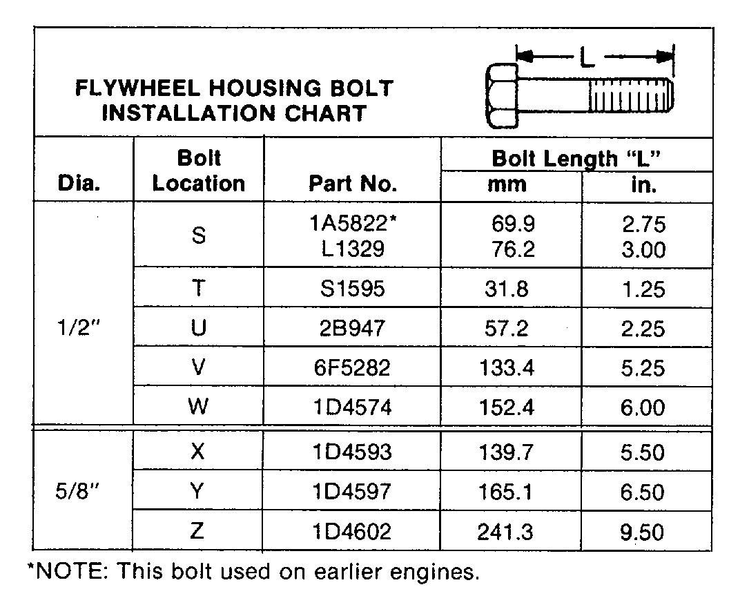
(1) Torque for plugs ........................70 + 15 N-m (50 + 11 lb. ft.) (2) Install three dowels to a height of .....................................6.0 + 0 5 mm ( 24 + .02 In.) (3) Tighten the bolts that hold the flywheel housing to the engine block evenly See FLYWHEEL HOUSING BOLT INSTALLATION CHART for correct position Torque for 1/2"-13 NC bolts ...........................................100 + 14 N-m (75 + 10 lb ft.) Torque for 5/8"-11 NC bolts ...........................................200 + 25 N-m (150 + 20 lb ft.)
NOTE: FOR TORQUE VALUES NOT GIVEN, SEE THE FIRST PAGE OF SPECIFICATIONS FOR GENERAL TIGHTENING TORQUES
51
FLYWHEEL HOUSING BORE
NOTE: Write the dial indicator measurements with their positive (+ and negative (-) notation (signs). This notation is necessary for making the calculations in the chart correctly.
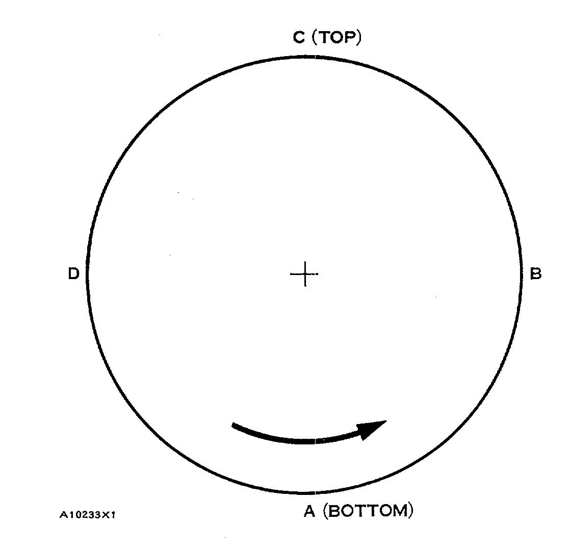
1. Fasten the dial indicator to the flywheel so the anvil of the indicator will touch the flywheel housing bore With the dial indicator In position at (C), adjust the dial Indicator to "O" (zero) Push the crankshaft up against the top bearing. Write the, measurement for bearing clearance on line 1 In column (C) 2. Divide the measurement from Step 1 by 2. Write this number on line 1 in columns (B) & (D). 3. Turn the crankshaft to put the dial Indicator at (A) Adjust the, dial indicator to "O" (zero). 4. Turn the crankshaft counterclockwise to put the dial Indicator at (B) Write the measurement in the chart. 5. Turn the crankshaft counterclockwise to put the dial Indicator at (C) Write the measurement In the chart. 6 Turn the crankshaft counterclockwise to put the dial indicator at (D). Write the measurement in the chart. 7 Add fines I and II by columns. 8 Subtract the smaller number from the larger number in line II In columns (B) & (D) The result is the horizontal "eccentricity (out of round). Line Ill, column (C) is the vertical eccentricity
CHART FOR DIAL INDICATOR MEASUREMENTS
Position of dial indicator
Line No. A B C D

Correction for bearing clearance I 0 Dial Indicator Reading II 0 Total of Line 1 & 2 III 0 ** * **
* Total Vertical eccentricity (out of round). ** Subtract the smaller No. from the larger No. The difference is
the total horizontal eccentricity. A10234X1
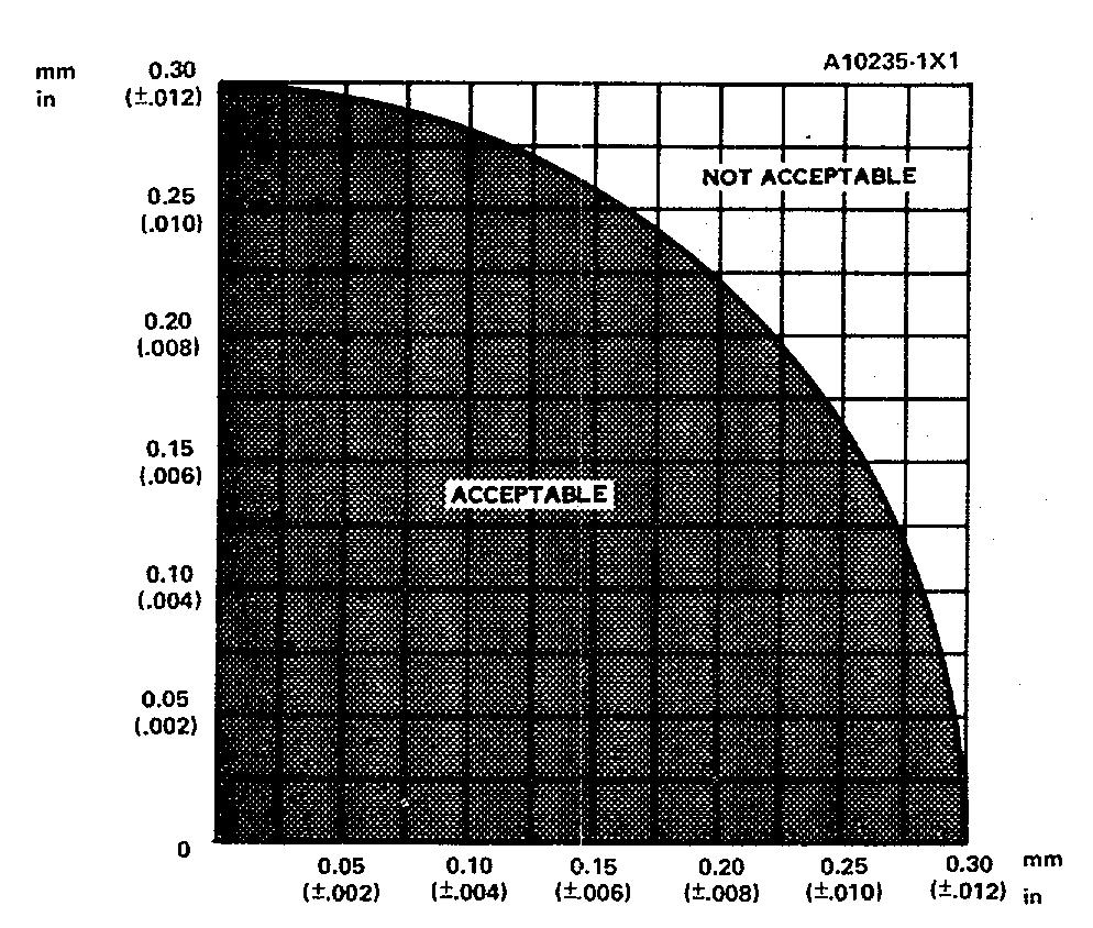
9 On the graph for total eccentricity find the point of intersection of the lines for vertical eccentricity and horizontal eccentricity 10 If the point of intersection Is In the range marked "Acceptable" the bore is In alignment If the point of intersection is In the range marked "Not Acceptable" the flywheel housing must be changed.