
1 minute read
Vibration Damper


DROOP ADJUSTMENT 10. Bracket.
8. Move governor terminal shaft (11) from the maximum position to the minimum position. The dial indicator must read 0.00 to 0.05 mm (.000 to .002 in.) for zero droop.
Advertisement
9. If the droop adjustment is not correct, loosen screw (9) and move droop cam (8). Tighten screw (9). Move droop cam (8) toward speeder plug (7) to increase droop, and away from the speeder plug to decrease droop.
10. Check the speed droop adjustment again with the dial indicator.
11. Install the shut-off strap in the governor.
12. Install the air fuel ratio control over the shut-off strap. Make sure lever (5) is engaged correctly with compensation lever (12) and install the screws to hold the unit to the governor.

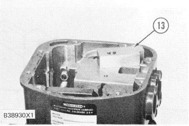
GOVERNOR ASSEMBLY 12. Compensation lever.
13. Make sure the O-ring seals are installed on the oil pressure line and into the air fuel ratio control. Install junction block (13). AIR FUEL RATIO CONTROL OIL LINE 13. Junction block.
GOVERNOR COVER ASSEMBLY 14. Oil level gauge. 15. Cover assembly.
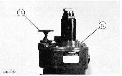
14. Install the shut-off actuator and cover assembly ( 15) on the air fuel ratio control housing. Install oil level gauge (14) in the cover assembly.
15. Connect the engine oil pressure and air inlet pressure lines to the air fuel ratio control housing.
Adjustment for Positive Droop
1. Remove the air fuel ratio control from the governor. See Steps I thru 6 in Adjustment for Zero Droop.
2. Connect a tachometer with good accuracy to the engine. Make reference to MEASURING ENGINE SPEED.
3. Loosen screw (9) and move droop cam (8) on droop lever ( 16) to get distance (A) for the droop percentage needed. See SPEED DROOP CHART to get the dimension needed.


