
4 minute read
Air Fuel Ratio Control


The crankshaft deflection must be checked after the final installation of the engine. The check must be made with the engine cold and also with the engine at the temperature of normal operation. The procedure that follows can be used to check crankshaft deflection with the engine either cold or warm.
1. Remove an inspection cover from the cylinder block that will give access to the connecting rod journal of the crankshaft nearest to the center of the engine.
Advertisement
2. Turn the crankshaft in the direction of normal rotation until the center of the counterweights just go beyond the connecting rod.
MEASURING DEFLECTION OF THE CRANKSHAFT (TYPICAL EXAMPLE) 1. Dial gauge. 2. Mounting face.
3. Install a Starrett Crankshaft Distortion Dial Gauge
No. 696 with Starrett No. 696B Balancer
Attachment between the counterweights as shown.
Put dial gauge (1) within 6.4 mm (.25 in.) of counterweight mounting surface (2). Turn the dial of the indicator to get alignment of the zero and the pointer. Turn the indicator on its end points until the pointer of the indicator will not move from zero. 4. 4.Turn the crankshaft in the direction of normal rotation until the indicator almost makes contact with the connecting rod on the other side of the crankshaft.
NOTE: Do not let the indicator make contact with the connecting rod.
5. The dial indicator reading must not change more than 0.03 mm (.001 in.) for the approximately 300 degrees of crankshaft rotation. Now turn the crankshaft in the opposite direction to the starting position. The dial indicator must now read zero. If the dial indicator does not read zero, do the procedure again.
If the dial indicator reads more than 0.03 mm (.001 in.), the cylinder block is bent. Loosen the bolts that hold the engine mounting rails to the foundation mounting rails and adjust the shims to make the engine straight again. Also check to see if the engine mounting bolts have enough clearance to let the engine have expansion as it gets hot.
VIBRATION DAMPER
Damage to or failure of the damper will increase vibrations and result in damage of the crankshaft.
If the damper is bent or damaged, or if the bolt holes in the damper are loose fitting, replace the damper. Replacement of the damper is also needed at the time of crankshaft failure (if a torsional type).
149
ELECTRICAL SYSTEM
TEST TOOLS FOR ELECTRICAL SYSTEM
Tools Needed: 6V4930 Battery Load Tester. 8T900 AC/DC Clamp-On Ammeter. 6V7070 Heavy-Duty Digital Multimeter or 6V7800 Regular-Duty Digital Multimeter.
Most of the tests of the electrical system can be done on the engine. The wiring insulation must be in good condition, the wire and cable connections must be clean and tight, and the battery must be fully charged. If the on-engine test shows a defect in a component, remove the component for more testing.
The service manual TESTING AND ADJUSTING ELECTRICAL COMPONENTS, Form No. REG00636 has complete specifications and procedures for the components of the starting circuit and the charging circuit.
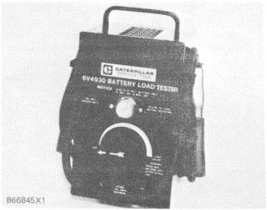
6V4930 BATTERY LOAD TESTER
The 6V4930 Battery Load Tester is a portable unit in a metal case for use under field conditions and high temperatures. It can be used to load test all 6, 8 an 12V batteries. This tester has two heavy-duty load cables that can easily be fastened to the battery terminals, and a load adjustment knob on the front panel permits a current range up to a maximum of 700 amperes. The tester also has a thermometer to show when the safe operating temperature limit of the unit has been reached. NOTE: Make reference to Special Instruction Form No. SEHS8268 for more complete information for use of the 6V4930 Battery Load Tester.
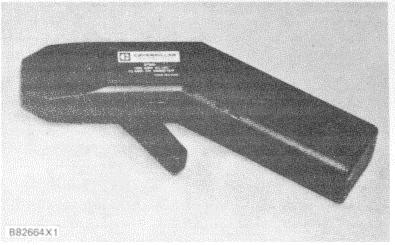
8T900 AC/DC CLAMP-ON AMMETER
The 8T900 AC/DC Clamp-On Ammeter is a completely portable, self-contained instrument that allows electrical current measurements to be made without breaking the circuit or disturbing the insulation on conductors. A digital display is located on the ammeter for reading current directly in a range from 1 to 1200 amperes. If an optional 6V6014 Cable is connected between this ammeter and one of the digital multimeters, current readings of less than 1 ammeter can then be read directly from the display of the multimeter.
A lever is used to open the jaws over the conductor [up to a diameter of 19 mm (.75 in.)], and the spring loaded jaws are then closed around the conductor for current measurement. A trigger switch that can be locked in the ON or OFF position is used to turn on the ammeter. When the turn-on trigger is re- leased, the last current reading is held on the display for 5 seconds. This allows accurate measurements to be taken in limited access areas where the digital display is not visible to the operator. A zero control is provided for DC operation, and power for the ammeter is supplied by batteries located inside the handle.
NOTE: Make reference to Special Instruction Form No. SEHS8420 for more complete information for use of the 8T900 Clamp-On Ammeter.


