2 minute read
Rear Gear Group


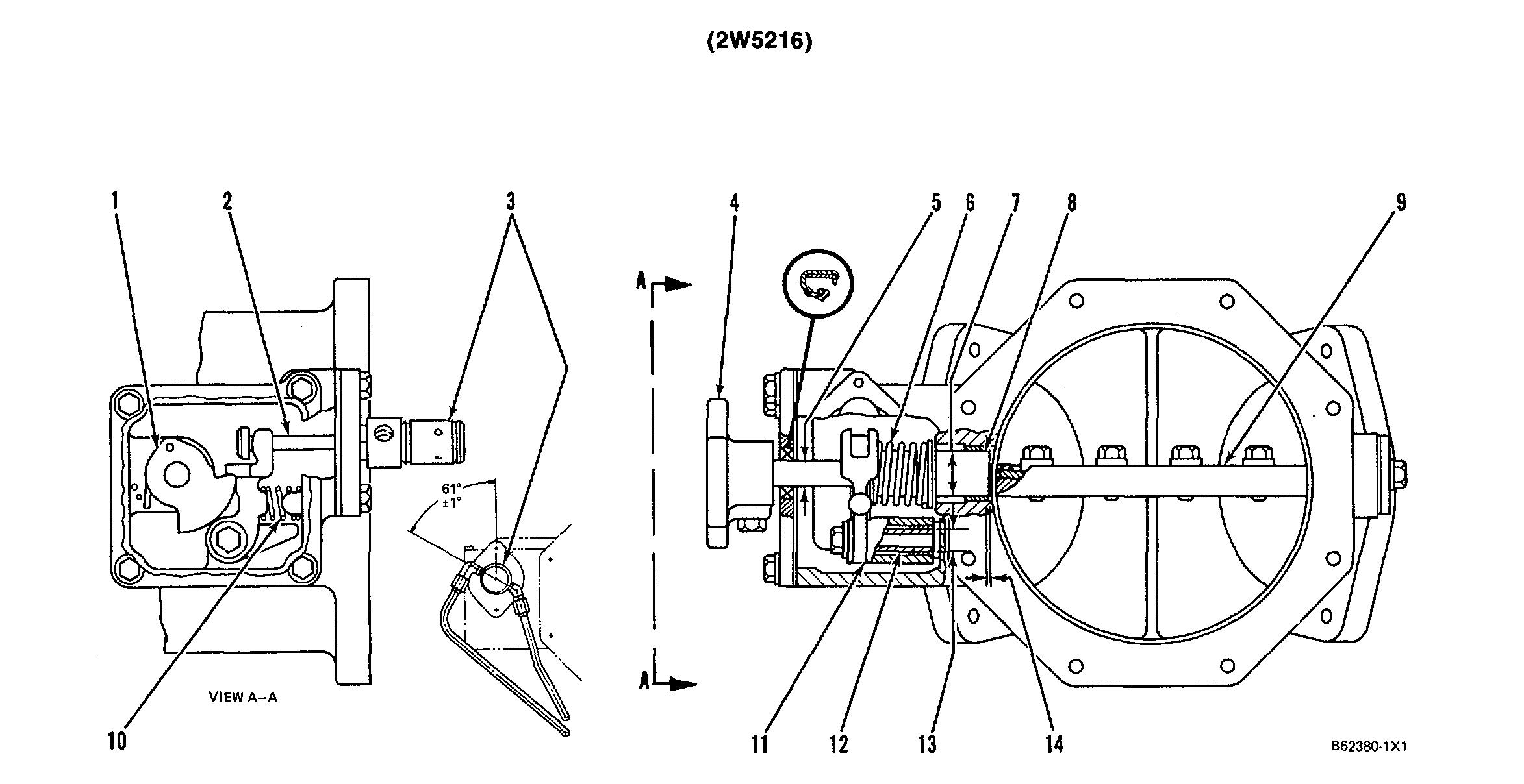
(1) Latch.
(2) Shutoff cylinder rod.
Advertisement
(3) Install shutoff cylinder as follows:
a. Assemble shutoff cylinder on the flange at the angle shown.
b. Tighten the nut that holds the shutoff cylinder to the flange to a torque of.... 45 ± 7 N•m (33 ±5 lb. ft.)
c. Install the flange on the air shutoff housing. Make sure cylinder rod (2) is engaged in the notch of lever (11).
NOTE: The cylinder vent hole, between the ports, must be in the downward position.
(4) Knob.
(5) Diameter of shaft assembly at seal .......15.88 ±0.05 mm (.625 ±.002 in.)
(6) Air shutoff spring.
(7) Diameter of shaft assembly.......24.88 ±0.02 mm (.980 ±.001 in.)
Bore in bushings for shaft assembly (after assembly)........ 25.017 ±0.040 mm (1.0035 ±0016 in.)
Bores in housing for bearings.......27.997 ±0.010 mm (1.1230 ±.0004 in.) (8) Shaft assembly. (9) Plate assembly.
NOTE: With plate assembly (9) in closed (shutoff) position, a 0.8 mm (.03 in.) feeler gauge must not pass between the plate assembly and the housing bore at any position.
(10) Lever return spring.
(11) Lever.
(12) Sleeve.
(13) Diameter of sleeve.................. 4.945 ± 0.009 mm (.5995 ±0004 in.)
Bore in bushing (after assembly)........5.024 ±0.034 mm (.6026 ±.0014 in.)
Bore in lever for
bushing.............7.009 ±0.009 mm (.6823 ±.0004 in.)
NOTE : Install both bushings to a dimension of 0.8 ±0.3 mm (.03 ±.01 in.) below the surface of lever ends.
(14) Dimension to install end of two bushings from machined
housing bore...0.35 ±0.15 mm (.014 ±.006 in.)
NOTE: FOR TORQUE VALUES NOT GIVEN, SEE THE FIRST PAGE OF SPECIFICATIONS FOR GENERAL TIGHTENING TORQUES
25
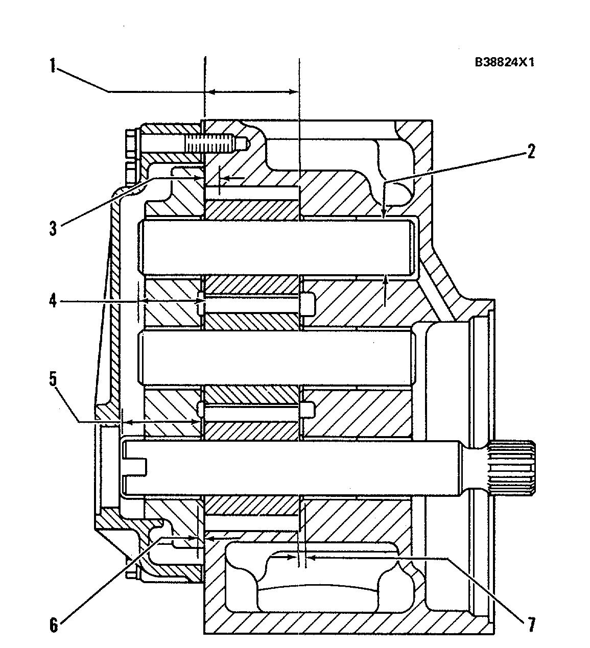
OIL PUMP (2W5474)
Rotation of drive gear (as seen from drive end) ................................Clockwise
(1) Length of gears (new) .......54.000 ±0.015 mm (2.1260 ±.0006 in.)
Depth of bores for gears (new) .......54.150 ±0.020 mm (2.1319 ±.0008 in.)
(2) Diameter of gear shafts (new)....31.742 ±0.008 mm (1.2497 ±.0003 in.)
Bore in bearings for gear shafts (after assembly)....... 31.811 ±0.013 mm (1.2524 ±.0005 in.)
(3) Distance dowels extend from cover......6.0 ±0.5 mm (.24 ±.02 in.)
(4) Distance from the end of the idler shafts to gear faces...........34.0 ±0.5 mm (1.34 ±.02 in.)
(5) Distance from the end of the drive shaft to gear face....47.0 ±0.5 mm (1.85 ±.02 in.)
(6) Depth that bearings are installed in cover .......1.5 ±0.5 mm (.06 ±.02 in.)
(7) Depth that bearings are installed in housing.......1.5 ±0.5 mm (.06 ±.02 in.)
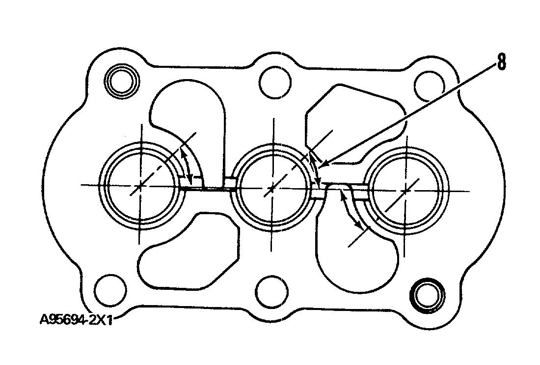
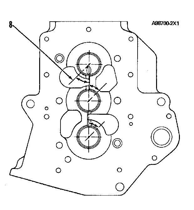
(8) The location of each bearing junction must be as shown. Position bearing junctions from the centerline through the bearing bores to an angle of ................................45 + 15°
(9) 2S2760 Spring (oil pressure relief):
Length under test force........117.9 mm (4.64 in.) Test force.......490 ±27 N (110 ±6 lb.) Free length after test......52.9 mm (6.02 in.) Outside diameter....27.00 mm (1.063 in.)