4 minute read
Front Drive Housing


HYDRAMECHANICAL SHUTOFF DRIVE
REMOVE HYDRAMECHANICAL SHUTOFF DRIVE
Tools Needed A
1P 1855 Pliers 1
start by: a) remove hydramechanical shutoff control b) remove tachometer drive
1. Remove tube assemblies (1) and (2) from the shutoff drive housing assembly and the engine.
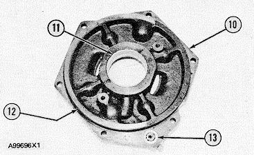
2. Remove the bolts and remove shutoff drive housing assembly (3) from the flywheel housing.
3. Use tool (A) to remove snap ring (5) and the washer from the end of drive gear (4). Remove drive gear (4) from the housing assembly.
4. If necessary, remove dowels (6) from the housing assembly.
5. Remove bearing (9) and seal (7) from the housing assembly. The bearing can be used to push the seal out of the bore.
6. Remove two bearings (8) from the drive gear bore.
7. If necessary, remove dowels (10) from the housing assembly.
8. Remove gear assembly ( 11 ) from the end of the crankshaft.
345
HYDRAMECHANICAL SHUTOFF DRIIVE
INSTALL HYDRAMECHANICAL SHUTOFF DRIVE
Tools Needed A B
1P510 Driver Group 1 1P 1855 Pliers 1
1. If necessary, make a replacement of dowels ( 1) in gear assembly (2). The dowels must extend 9.5 + 0.5 mm (.374 + .020 in.) from the gear. Put gear assembly (2) in position on the end of the camshaft and install the bolts to hold it. Tighten the bolts evenly to a torque of 100 + 15 N•m (75 + 10 lb. ft.). Hit the gear assembly with a hammer and tighten the bolts again to the same torque. Do this until the torque does not change.
2. If dowels (5) were removed, install the new dowels until they extend 6.0 + 0.5 mm (.236 + .020 in.) from the housing assembly.
3. Use tool group (A) to install two bearings (4) in the drive gear bore until they are 1.5 + 0.5 mm (.059 + .020 in.) from the ends of the bore.
4. Put drive gear (3) in position in the housing assembly.
5. Put washer (8) in position and use tool (B) to install snap ring (7) to hold the washer and drive gear in position.
6. Use tool group (A) to install bearing (6) in the housing assembly until it is 26 ± 1 mm (1.02 + .04 in.) below surface (X). Use tool group (A) and install seal (10) to the bottom of the bore. Make sure the lip of the seal is toward the engine as shown and put clean engine oil on the lip.
7. If dowels (9) were removed, install the new dowels until they extend 6.0 + 0.5 mm (.236 + .020 in.) from the housing.
8. Install shutoff drive housing assembly (13) and the bolts to hold it on the flywheel housing. Make sure the teeth of drive gear (3) are correctly engaged with the teeth of gear assembly (2).
9. Install tube assemblies (11) and (12) on the X housing assembly and the engine. end by: a) install hydramechanical shutoff control b) install tachometer drive
346
ACCESSORY DRIVE (FRONT)
REMOVE ACCESSORY DRIVE (FRONT) 1207-11
start by: a) remove governor drive b) remove alternator (if so equipped)
1. Remove the bolts and remove cover (1) from adapter assembly (2).
2. Use two 1/2"-13 NC forcing screws to remove adapter assembly (2) from the front drive housing.
3. Remove the bolts and remove adapter assembly (3), the drive gear and shaft as a unit from the front drive housing.
INSTALL ACCESSORY DRIVE (FRONT) 1207-12
1. Make sure the two O-ring seals are in position on adapter assembly (1) and put clean engine oil on them.
2. Install the drive shaft, gear and adapter assembly (1) in the front drive housing. Make sure the teeth of the accessory drive gear are correctly engaged with the teeth of the oil and water pump drive gear and install the bolts to hold adapter assembly (1) in position.
3. Make sure the two O-ring seals are installed on adapter assembly (2) and put clean engine oil on the seals. Put clean oil on the lip of the seal and bearing in adapter assembly (2) and install the adapter assembly. Tighten the bolts to hold adapter assembly (2) in position.
4. Install the cover on adapter assembly (2). end by: a) install governor drive b) install alternator (if equipped)
ACCESSORY DRIVE (FRONT)
DISASSEMBLE ACCESSORY DRIVE (FRONT) 1207-15
Tools Needed A 1P520 Driver Group 1
start by: a) remove accessory drive (front)
1. Remove O-ring seals (2) and (3) from the adapter.
2. Remove seal (4) from adapter (1). Use a press and tool group (A) to remove bearing (5) from adapter (1).
3. Remove bolts (7) to remove gear (8) from shaft (6).
4. Remove bolts (9) and the retainer washer to remove shaft (6) from adapter (10).
5. Remove O-ring seals (12) and (13) from adapter (10).
6. Use a press and tool group (A) to remove bearing (11) from adapter (10)


