6 minute read
Hydraulic Circuits, Later with an Alarm System


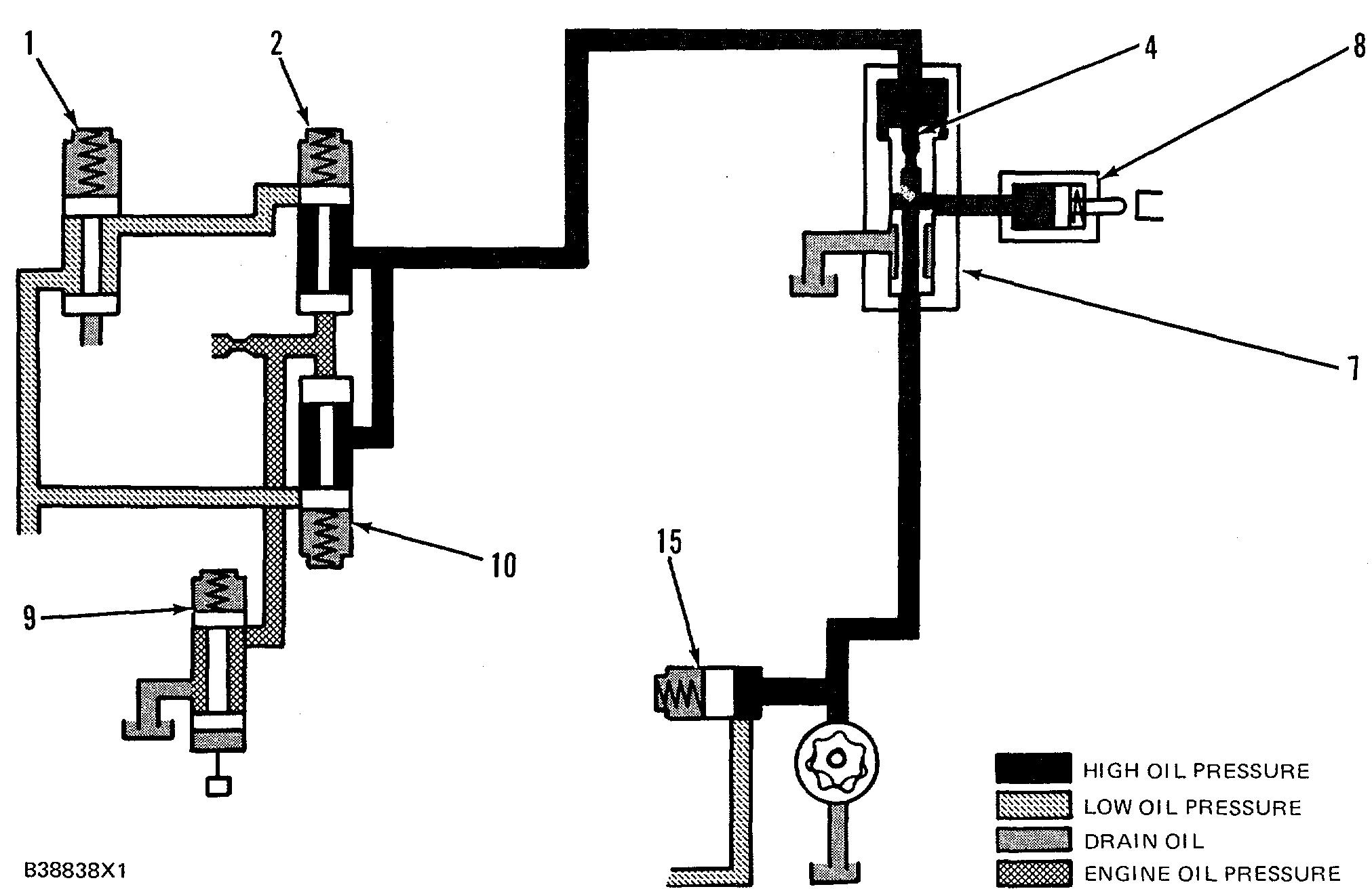
SCHEMATIC NO. 3 (LOW ENGINE OIL PRESSURE FAULT) (Low Speed Range) 1. Selector valve. 2. Low speed oil protection valve. 4. Diverter valve orifice. 6. Speed sensing valve spool. 7. Diverter valve. 8. Fuel shutoff actuator. 10. High speed oil protection valve. 15. Fuel shutoff sequence valve. 17. Oil pump.
LOW SPEED RANGE (LOW ENGINE OIL PRESSURE FAULT)
Make Reference to Schematic No. 3
If the engine oil pressure goes below 140 kPa (20 psi), the spring force on low speed oil protection valve (2) will close the valve. The oil flow in the circuit is then stopped and can not flow to drain. The pressure of the oil will become equal to both sides of diverter valve orifice (4). Spring force will move the valve spool of diverter valve (7) down so that there is alignment with the passage that leads to fuel shutoff actuator (8). Oil pressure will now activate the fuel shutoff actuator, which will cause the governor to move the fuel control linkage to the "SHUTOFF" position and shutdown the engine.
217
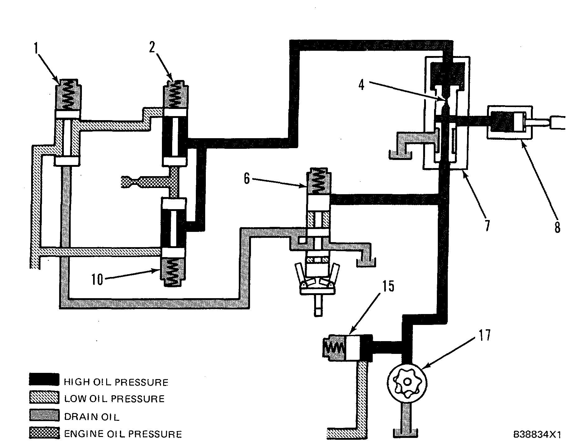
SCHEMATIC NO. 4 (LOW ENGINE OIL PRESSURE CIRCUIT) (High Speed Range) 1. Selector valve. 2. Low speed oil protection valve. 4. Diverter valve orifice. 6. Speed sensing valve spool. 7. Diverter valve. 8. Fuel shutoff actuator. 10. High speed oil protection valve. 12. Air inlet shutoff actuator. 13. Air inlet sequence valve. 14. Pilot operated two-way valve. 15. Fuel shutoff sequence valve. 16. Air inlet shutoff valve. 17. Oil pump. 18. Oil pressure relief valve.
HIGH SPEED RANGE (NORMAL ENGINE
OIL PRESSURE) Make Reference to Schematic No. 4
At approximately 70% of engine full load speed, the oil pressure protection changes from the low speed range to the high speed range. At this point engine oil pressure is high enough to open high speed oil protection valve (10).
System oil flow to diverter valve (7) is the same as it is for the low speed range except speed sensing valve spool (6) has been shifted. When the engine speed increases to the high speed range, speed sens- ing valve spool (6) will be moved up by the fly- weights. This directs system oil pressure at 760 kPa (110 psi) to selector valve (1). The valve closes toL/ remove low range oil pressure protection valve (2) from the circuit. The oil now flows from diverter valve (7) to drain through high speed oil protection valve (10) and pilot operated two-way valve (14).
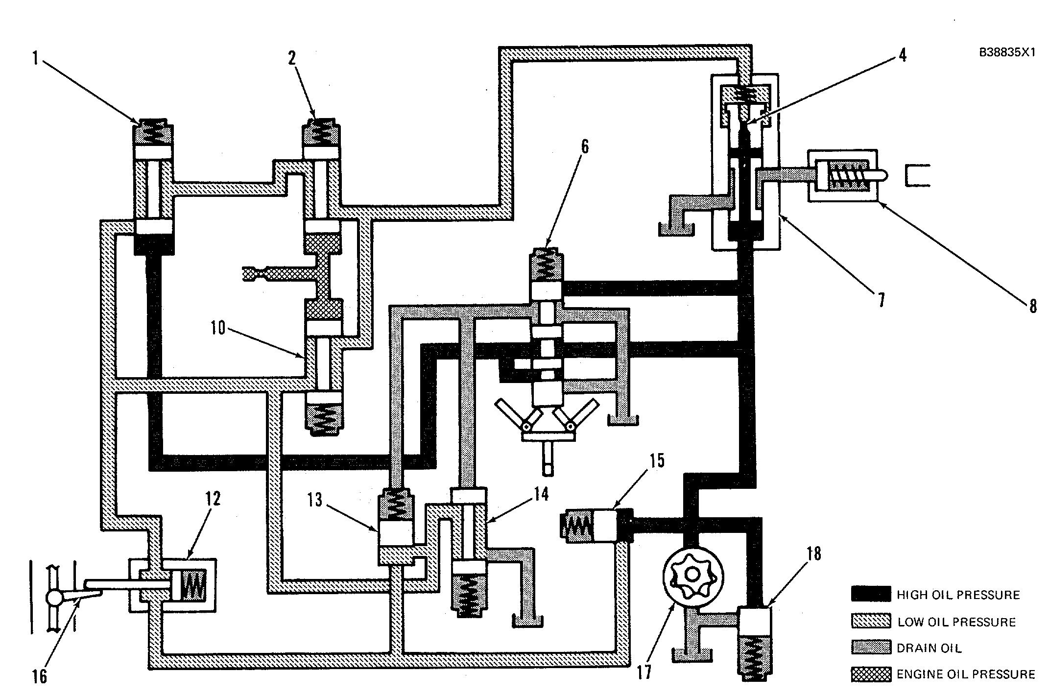
SCHEMATIC NO. 5 (LOW ENGINE OIL PRESSURE FAULT) (High Speed Range) 1. Selector valve. 2. Low speed oil protection valve. 4. Diverter valve orifice. 6. Speed sensing valve spool. 7. Diverter valve. 8. Fuel shutoff actuator. 10. High speed oil protection valve. 15. Fuel shutoff sequence valve. 17. Oil pump.
HIGH SPEED RANGE (LOW ENGINE OIL PRESSURE FAULT)
Make Reference to Schematic No. 5
When engine oil pressure decreases to 205 kPa (30 psi), the spring force on high speed oil protection valve (10) will move the valve to stop oil flow to the drain. The difference in oil pressure across diverter valve orifice (4) will now go to zero. The valve spool of diverter valve (7) will move down by spring force, which will cause alignment of the ports to fuel shutoff actuator (8). The actuator now causes the governor to move the fuel control linkage to the "SHUT- OFF" position and shutdown the engine.
219
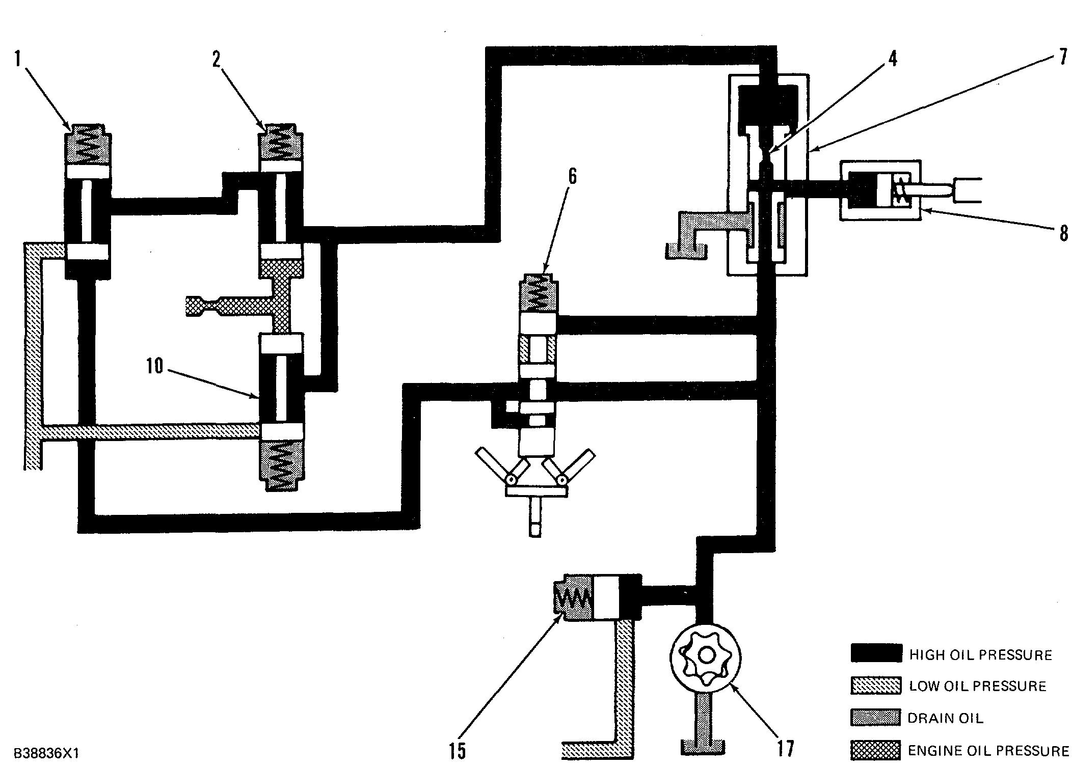
SCHEMATIC NO. 6 (ENGINE COOLANT TEMPERATURE CIRCUIT) (Low Speed Range Shown) 1. Selector valve. 2. Low speed oil protection valve. 4. Diverter valve orifice. 7. Diverter valve. 8. Fuel shutoff actuator. 9. Thermostatic pilot valve. 10. High speed oil protection valve. 15. Fuel shutoff sequence valve.
HIGH, ENGINE COOLANT TEMPERATURE CIRCUIT (NORMAL CONDITIONS)
Make Reference to Schematic No. 6

Under high coolant temperature conditions, the low engine oil pressure circuits are used to shutdown an engine. The schematic shows the low speed range engine oil pressure circuit in use and the coolant temperature circuit added to the engine oil pressure line. Engine temperature is normal and thermostatic pilot valve (9) is closed.
Oil flow through the system is the same as in the low and high speed range of the LOW ENGINE OIL PRESSURE CIRCUIT.
NOTE: The sensor of the thermostatic pilot valve (9) must be below the water level in the coolant manifold to operate.
220
SCHEMATIC NO. 7 (HIGH ENGINE COOLANT TEMPERATURE FAULT) 1. Selector valve. 2. Low speed oil protection valve. 4. Diverter valve orifice. 7. Diverter valve. 8. Fuel shutoff actuator. 9. Thermostatic pilot valve. 10. High speed oil protection valve. 15. Fuel shutoff sequence valve.
HIGH ENGINE COOLANT TEMPERATURE CIRCUIT (FAULT CONDITION)
Make Reference to Schematic No. 7
When engine coolant temperature increases to 99°C (2100F), thermostatic pilot valve (9) will open. This will let engine oil in the circuit drain and cause a decrease in oil pressure on low speed oil protection valve (2) and high speed oil protection valve (10). Valves (2) and (10) will close and stop oil flow from diverter valve (7). The difference in oil pressure across diverter valve orifice (4) will now go to zero. The valve spool of diverter valve (7) will move down by spring force, which will cause alignment of the ports to fuel shutoff actuator (8). The actuator now causes the governor to move the fuel control linkage to the "SHUTOFF" position and shutdown the engine.
221
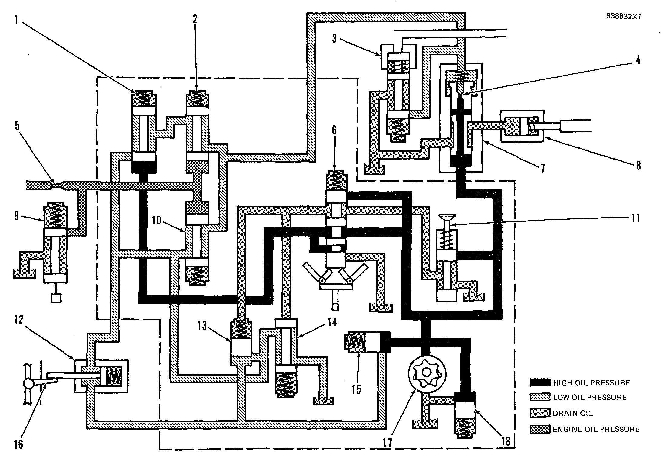
OVERSPEED CIRCUIT (NORMAL CONDITIONS)
Make Reference to Schematic No. 8
When an engine is started and speed increases, engine oil pressure opens low speed oil protection valve (2) and high speed oil protection valve (10). At the same time, oil in the protective system flows from oil pump (17) to fuel shutoff sequence valve (15), speed sensing valve spool (6) and diverter valve (7). Fuel shutoff sequence valve (15) keeps the oil pressure to diverter valve (7) and speed sensing valve spool (6) at 760 kPa (110 psi) and then directs the remainder of oil flow through the air inlet shutoff circuit. At higher engine speeds, speed sensing valve spool (6) directs oil pressure to close selector valve (1).
Oil in the air inlet shutoff circuit is directed to air inlet sequence valve (13) and air inlet shutoff actuator (12). Air inlet sequence valve (13) keeps the oil pressure in air inlet shutoff actuator (12) at 105 kPa ( 15 psi) and then directs the remainder of oil flow to drain through pilot operated two-way valve (14), which is normally open. Pilot operated two-way valve (14) is held open by spring force and the pilot oil pressure is connected to the drain through speed sensing valve spool (6).
At diverter valve (7), the oil flows through orifice (4) which causes a pressure difference across both ends of the valve spool. The valve spool is then moved by system oil pressure, against a spring force, to keep the fuel shutoff actuator from being operated. The oil then flows from diverter valve (7) to drain through high speed oil protection valve (10) and pilot operated two-way valve (14).
NOTE: Low engine oil pressure or high coolant temperature conditions do not change the oil flow in the air inlet shutoff circuit.
222
SCHEMATIC NO.8 (OVERSPEED CIRCUIT) 1. Selector valve. 2. Low speed oil protection valve. 3. Start-up override valve. 4. Diverter valve orifice. 5. Engine oil pressure orifice. 6. Speed sensing valve spool. 7. Diverter valve. 8. Fuel shutoff actuator. 9. Thermostatic pilot valve. 10. High speed oil protection valve. 11. Emergency manual shutoff valve. 12. Air inlet shutoff actuator. 13. Air inlet sequence valve. 14. Pilot operated two-way valve. 15. Fuel shutoff sequence valve. 16. Air inlet shutoff valve. 17. Oil pump. 18. Oil pressure relief valve.
223