1 minute read
System Checks


HYDRAULIC CIRCUITS (LATER)
(With Check Valves in Diverter Valve)
Later hydramechanical protective systems have hydraulic circuits that use check valves to hold hydraulic pressure on (lock) the fuel shutoff actuator in the "SHUTOFF" position, after the engine has been shutdown. In this system, the start-up override valve must be operated to release the hydraulic pressure from the fuel shutoff actuator before the engine can be started. Also, make sure the air inlet shutoff is in the open position before the engine is started.
The operation of these hydraulic circuits is the same as that of the earlier hydraulic circuits except for the check valves in the diverter valve for the fuel shutoff circuit.
START-UP OVERRIDE
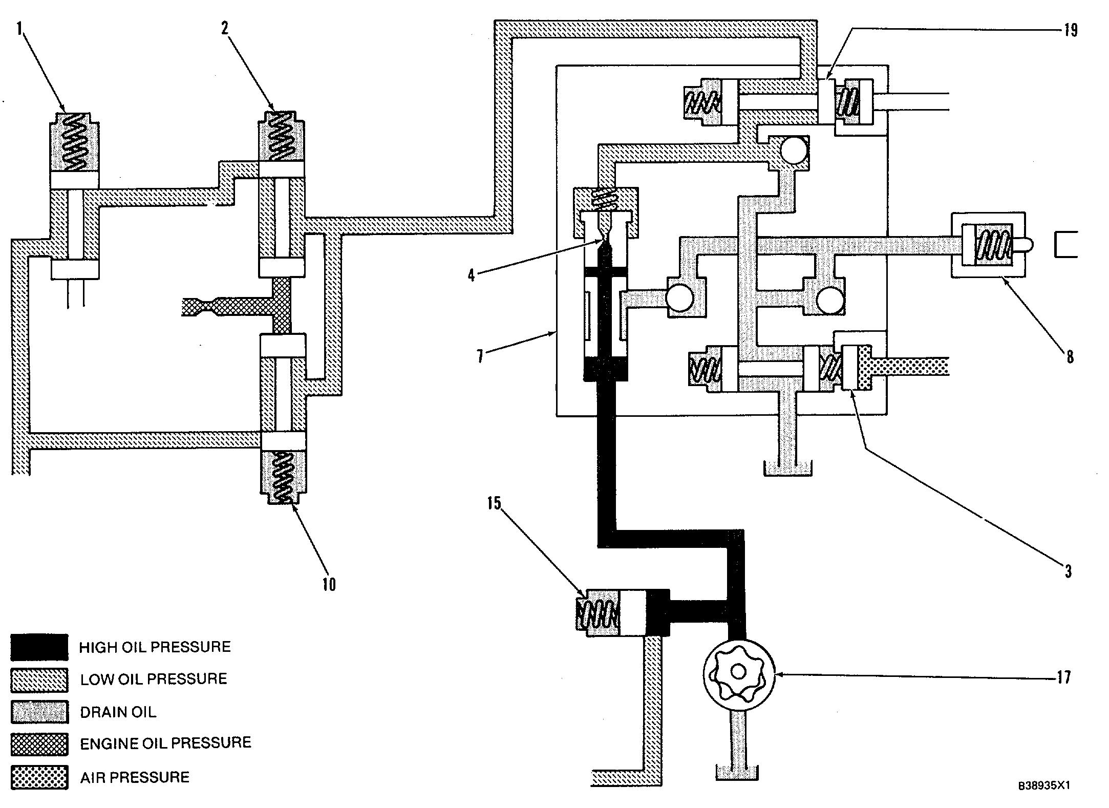
Make Reference to Schematic No. 13
When operated, the start-up override valve connects the fuel shutoff actuator circuit to drain. This removes any hydraulic pressure on the actuator so the governor can move the fuel control linkage and the engine can be started.
Also, on hot restart, after severe operating conditions, the engine oil pressure can increase slowly. If the rate of pressure increase is too slow, the protective system activates actuator (8) to move the fuel control linkage to the "SHUTOFF" position be- cause of a low engine oil pressure fault. Therefore, an override of the low engine oil pressure circuit is needed in the protective system.
An electric solenoid or air operated start-up override valve (3) is installed in the diverter valve return line. The valve is normally closed. When start-up override valve (3) is operated, the outlet of the di- verter valve is connected to drain. This maintains a pressure drop across orifice (4) and does not let the diverter valve shift to the shutdown position. The fuel shutoff actuator line is also connected to drain to make sure fuel shutoff actuator (8) does not hold the governor shutoff strap in the off position.
When start-up override valve (3) is not in use, the engine oil circuit is put back into normal operation as in Schematics No. 2 and No. 4.


